ISO 9001:2015 certification mark

ISO 9001:2015 Certified by SGS

IMPELLER COMPONENT CAPABILITIES

Open and Closed Impellers for Replacement Requirements

We support the development of open and closed impeller components from available drawings, CAD data, scan data, or existing parts. Each requirement is reviewed individually according to its geometry, material specification, quantity, manufacturing needs, and inspection requirements.

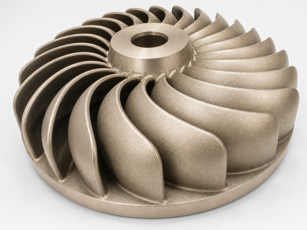
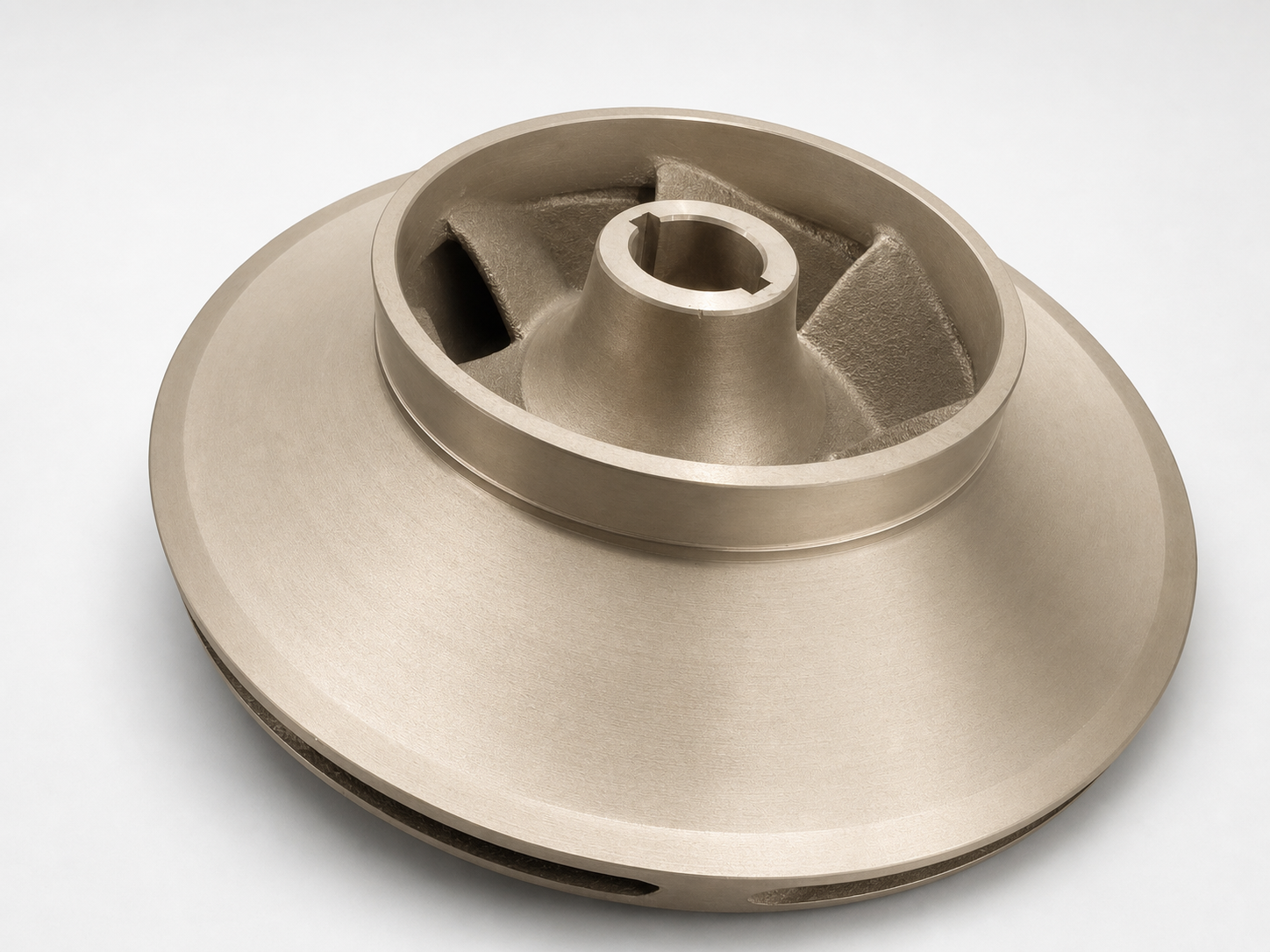
Closed impeller viewed from a three-quarter angle
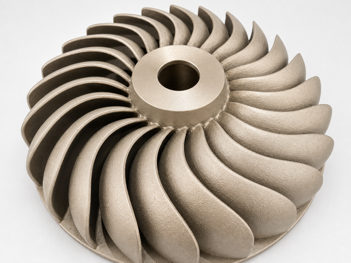
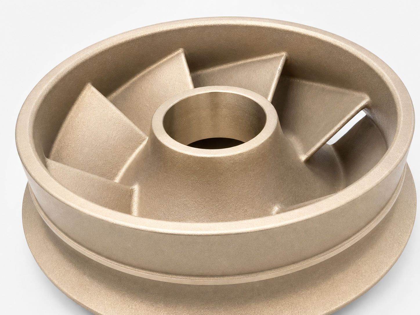
Open impeller with visible blade arrangement
Closed impeller with shrouded blade geometry
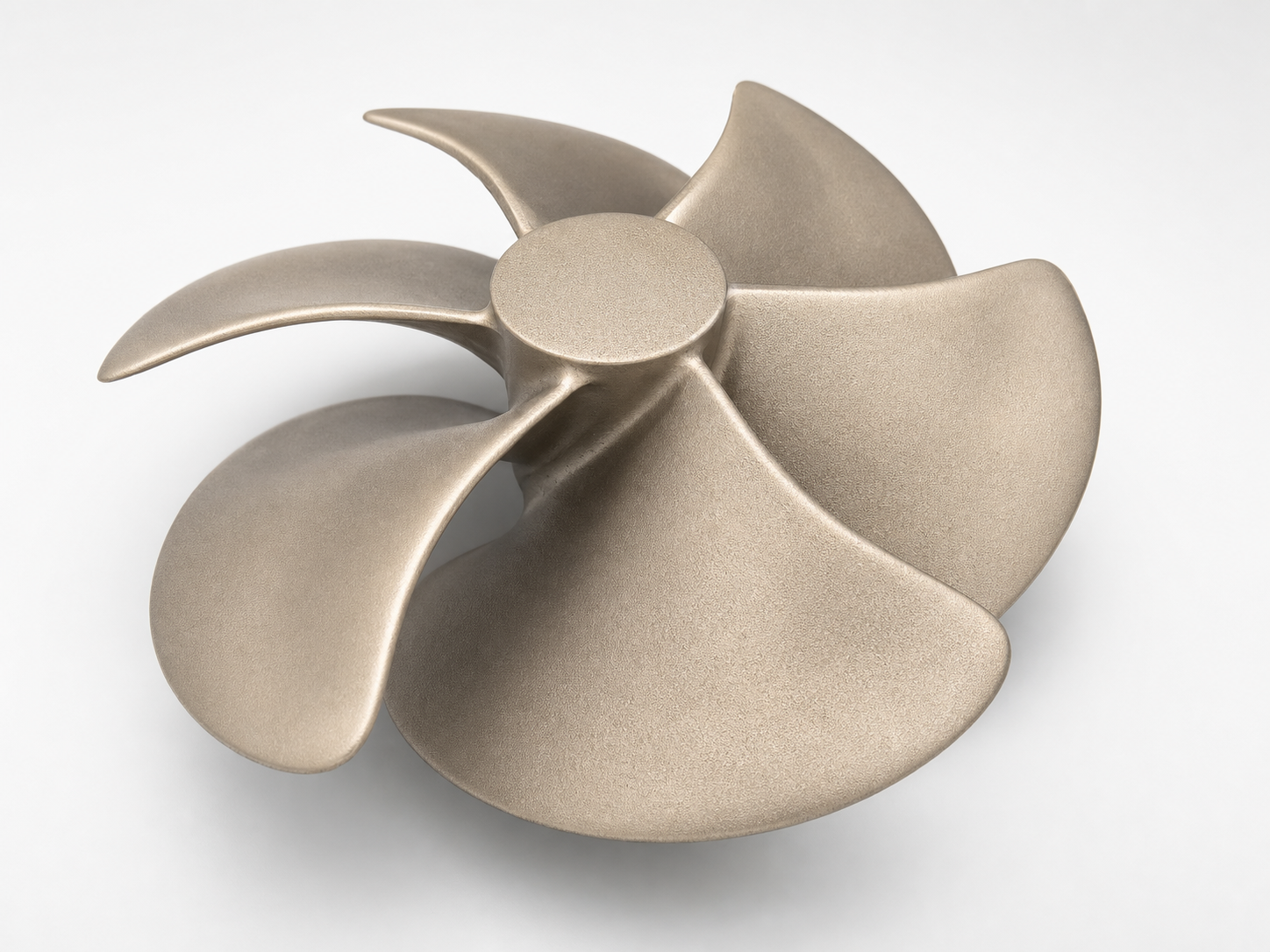
Open impeller with multi-blade geometry

Impeller Configurations

The examples below show two observable impeller configurations. The manufacturing approach for an actual requirement must be determined from the supplied geometry, material specification, quantity, and inspection requirements.

Closed impeller viewed from a three-quarter angleClosed impeller with shrouded blade geometry
Closed

Closed Impellers

Closed impellers incorporate enclosed flow passages between the front and rear shrouds. Their internal blade and passage geometry requires careful review during geometry preparation and manufacturing planning.

View Closed Impeller Examples
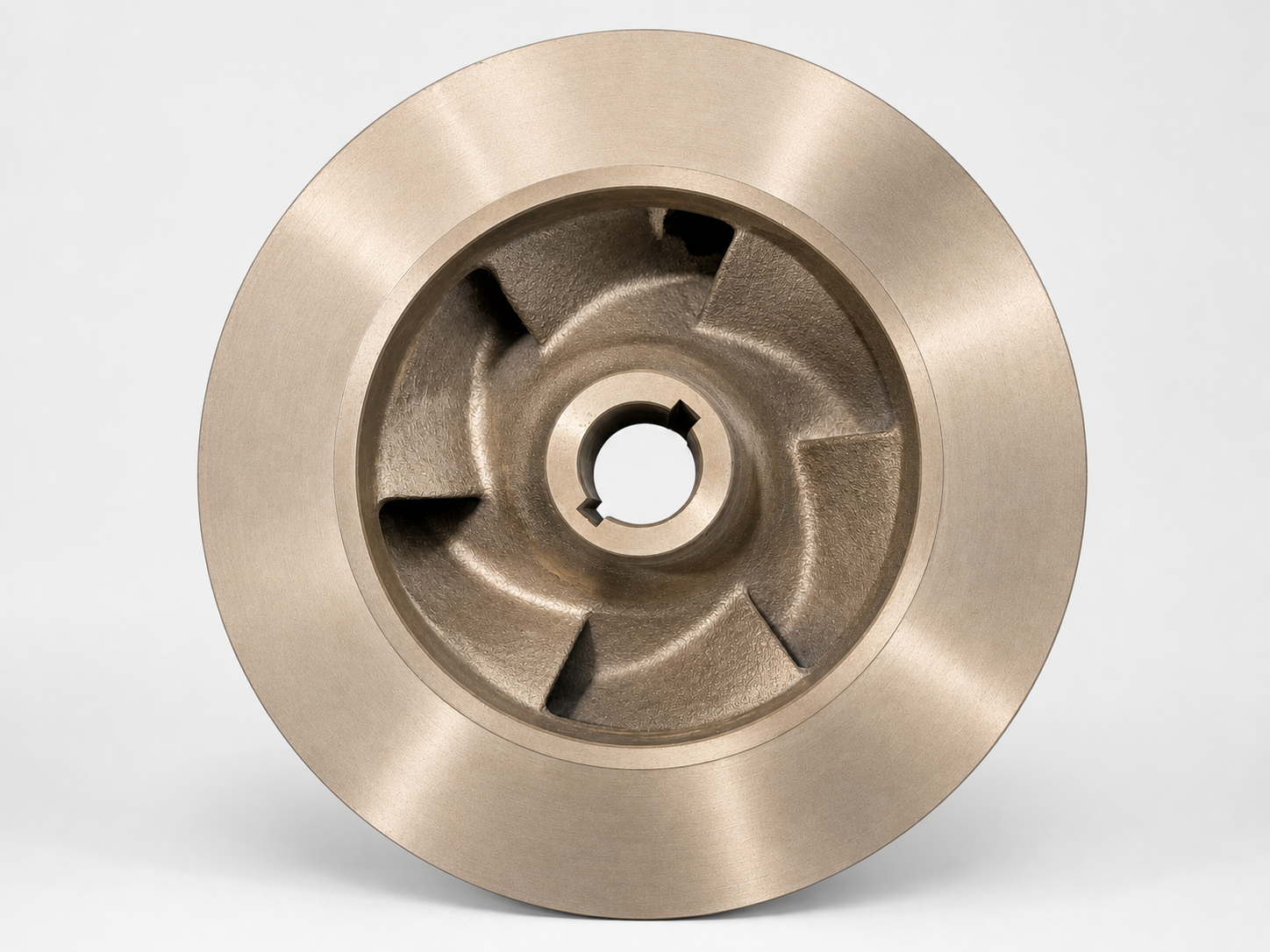
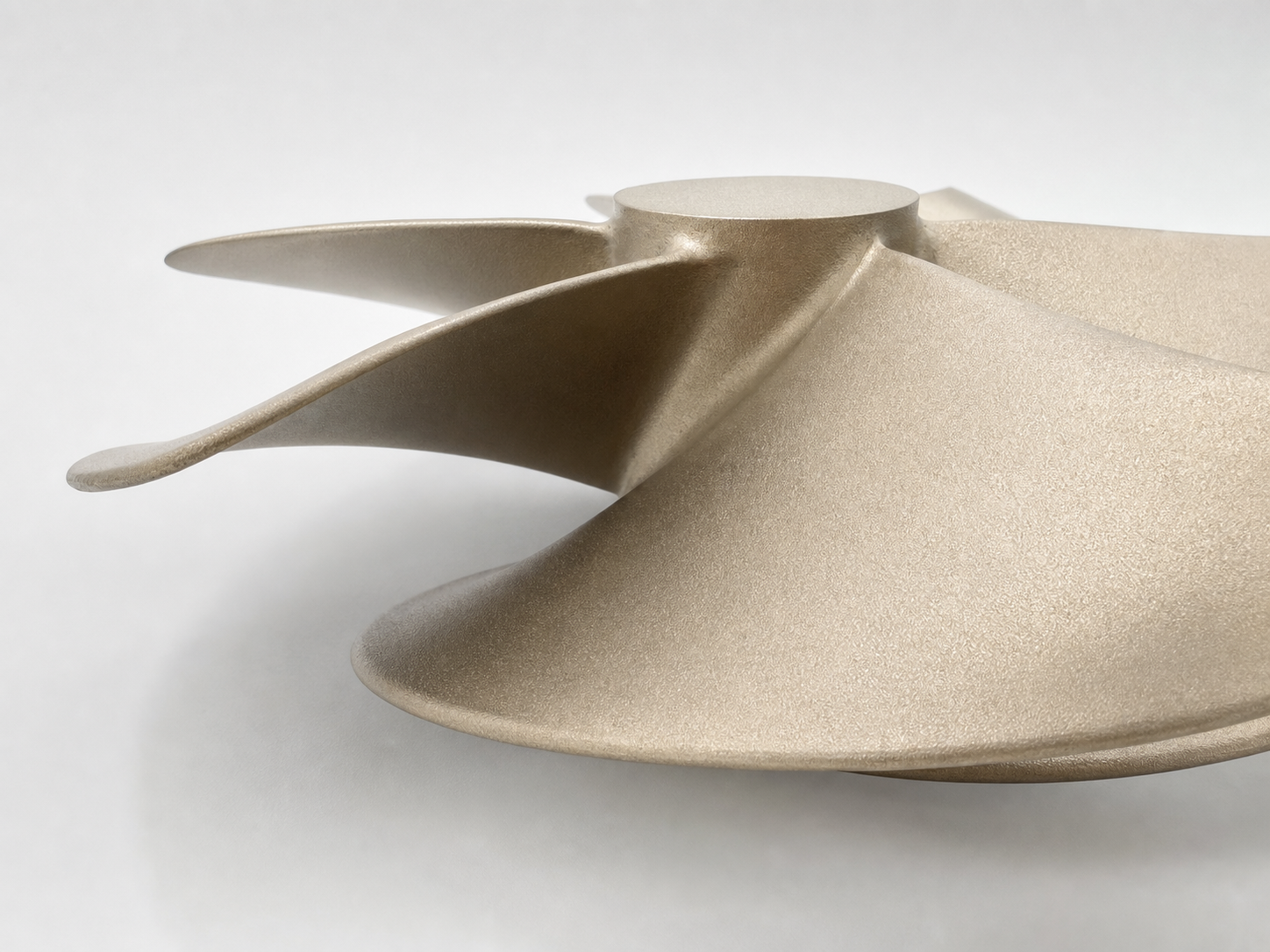
Open impeller with visible blade arrangementOpen impeller with multi-blade geometry
Open

Open Impellers

Open impellers have exposed blade geometry, allowing the blade arrangement, curvature, hub, and accessible flow surfaces to be directly observed.

View Open Impeller Examples

Geometry Requiring Careful Technical Review

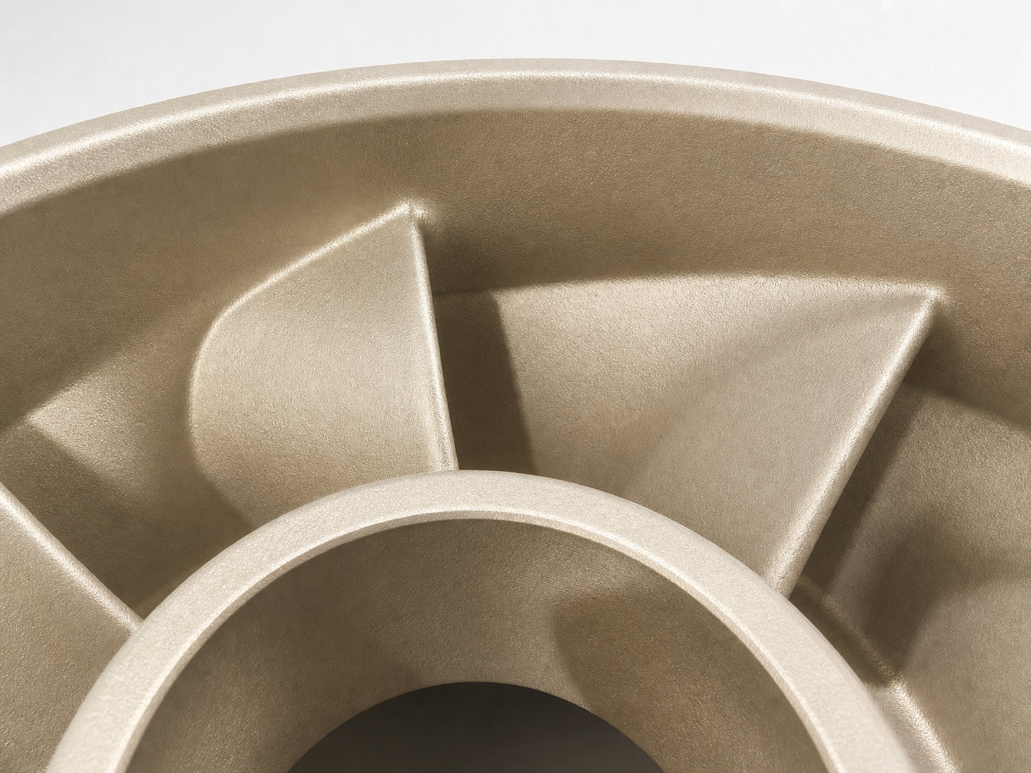
Inlet and internal blade detail of a closed impeller
Enclosed Flow Passages

Internal passages must be reviewed according to the supplied geometry and manufacturing requirements.

Close-up of curved open impeller blades
Blade Curvature and Spacing

Blade shape, spacing, and accessibility are important considerations during geometry and manufacturing preparation.

Angled view showing open impeller hub and blade curvature
Hub and Connection Geometry

The hub and connection area must be reviewed against the supplied drawing, CAD data, or existing component.

Closed impeller hub and shrouded blade arrangement
Open and Closed Configurations

Different configurations may require different geometry preparation and manufacturing considerations.

Start with the Information You Have

Drawing

Review available drawings, dimensions, and technical specifications.

CAD Data

Assess supplied digital geometry for technical and manufacturing preparation.

Scan Data

Use available scan data as a reference when geometry information is incomplete.

Existing Component

Review an available component or clear photographs when drawings or CAD data are unavailable.

The suitable workflow depends on the available information and the technical requirements of each component.

Typical Impeller Development Workflow

Typical Project Workflow
  1. 1
    Drawing, CAD, Scan Data, or Existing Part
  2. 2
    Technical Review
  3. 3
    Geometry Preparation
  4. 4
    Manufacturing Planning
  5. 5
    Casting and Machining
  6. 6
    Inspection

The actual workflow is determined by the component geometry, material specification, available reference data, quantity, and inspection requirements.

Need to Reproduce or Develop an Impeller?

Send an available drawing, CAD file, scan data, or clear photographs of the existing component for an initial technical discussion.

Technology Representation

ExOne logo

ExOne Sales Representative in Thailand

Speed 3D Mold Co., Ltd. is listed by ExOne as a sales representative in Thailand, supporting local coordination for industrial sand 3D-printing solutions.

Verify our listing on ExOne’s official global support network.

View Official ExOne Listing

MEMBERS & SOCIETIES

Thai Foundry Association
FTI