ISO 9001:2015 certification mark

ISO 9001:2015 Certified by SGS

Additive Manufacturing Service

3D Sand Printing for Industrial Metal Casting

Patternless production of sand molds and complex cores from verified CAD data—integrated with casting simulation, metal casting and inspection.

We print the sand molds and cores—not the final metal component. The printed mold is subsequently used in the metal casting process.

View Documented Projects
  • Industrial binder-jet sand printing
  • ExOne S-Max system
  • Patternless molds and complex cores
  • Integrated engineering-to-casting workflow
  • Thailand-based engineering and production
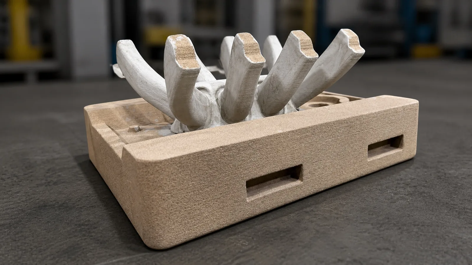
Binder-jet printed sand mold and core package produced for an industrial metal casting
Printed sand mold and core package produced from prepared digital data.

When 3D Sand Printing Becomes the Practical Casting Route

3D sand printing is not automatically cheaper or faster than a conventional route. The appropriate production route depends on geometry, quantity, material, tolerance, inspection requirements and schedule.

No Original Pattern Available

For obsolete or replacement components where the original tooling is missing, damaged, or no longer available.

Low-Volume or One-Off Production

For projects where conventional pattern tooling would add disproportionate cost or lead time relative to the quantity required.

Complex Internal Geometry

For components requiring complex cores, internal passages, undercuts, or geometries that are difficult to produce conventionally.

Urgent Engineering Requirements

For projects where the customer needs to shorten the mold-and-core preparation stage of the casting programme.

How an Additive Manufacturing Casting Project Can Start

A project may begin from complete engineering data or from the component itself. The starting point determines how much reconstruction work is required before mold and core production.

Projects without usable CAD data: Reverse Engineering
  • 2D engineering drawings
  • Existing CAD data
  • 3D scan data
  • A worn or damaged physical component
  • An existing pattern or core box requiring redesign
  • Performance or dimensional requirements

From Project Data to Verified Casting

The exact workflow and inspection scope are defined according to the component, alloy, quantity, condition of the available data and customer requirements. Not every project uses every stage.

  1. 01

    Requirement Review

    Input
    Drawing, CAD, scan data, sample component, quantity, alloy and delivery requirement.
    Activity
    Project feasibility and manufacturing-route review.
    Output
    Proposed engineering and production route.
  2. 02

    Geometry Preparation

    Input
    Available or reconstructed geometry and material specification.
    Activity
    CAD verification, casting allowances, machining allowances, parting strategy and core development.
    Output
    Casting-ready geometry.
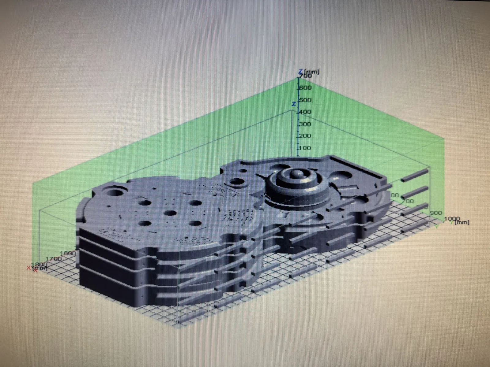
    Digital build layout of sand mold and core sections prepared before printing
    Prepared mold and core data arranged for the printing build.
  3. 03

    Casting Simulation

    Input
    Casting-ready geometry, proposed gating and feeding layout.
    Activity
    Evaluation of filling, solidification, gating and feeding strategy where required for the project.
    Output
    Reviewed casting-process proposal.
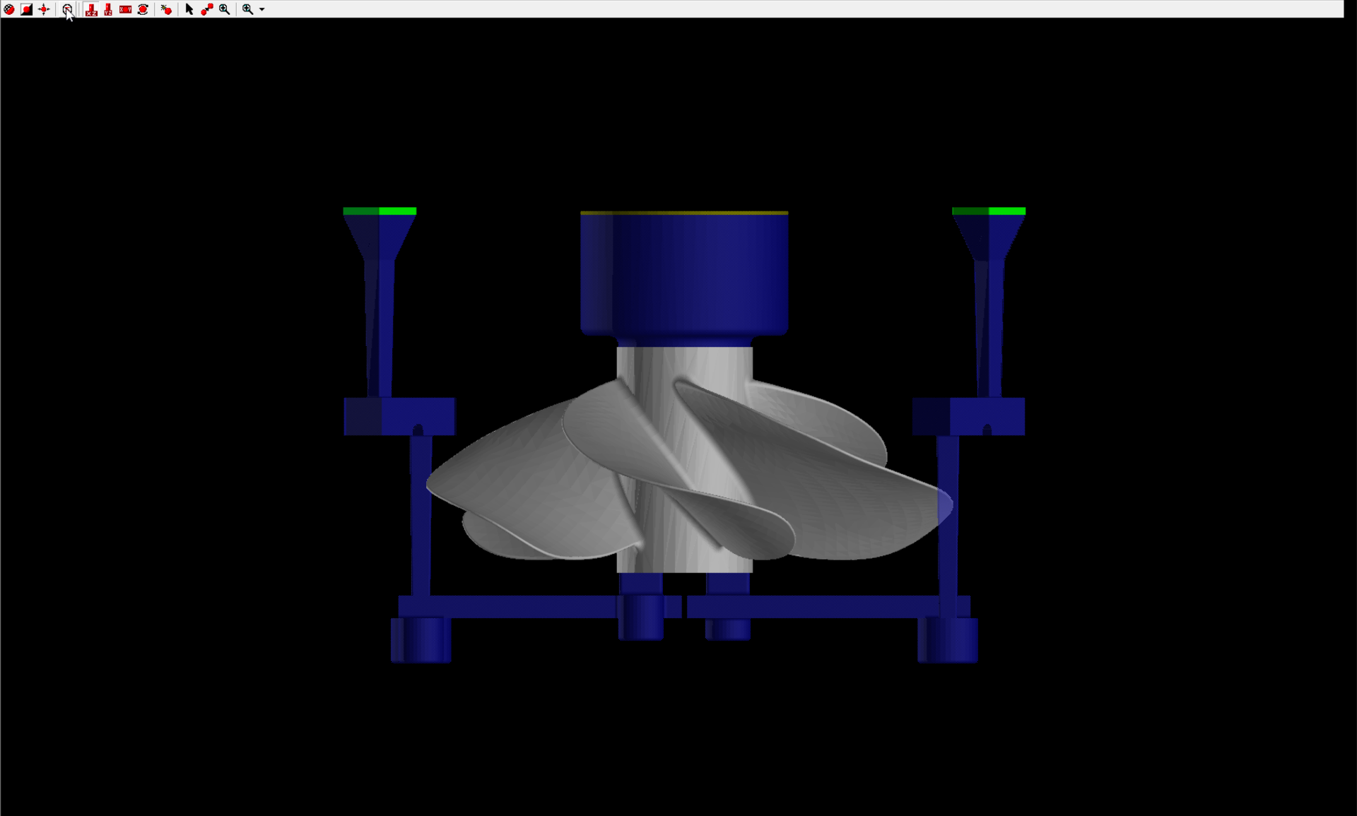
    Casting simulation result showing mold filling behaviour of a cast component
    Mold-filling review carried out before mold and core production, where applicable.
  4. 04

    Mold and Core Printing

    Input
    Approved mold and core data.
    Activity
    Print data preparation, component orientation and production of binder-jetted silica-sand molds and cores.
    Output
    Casting-ready mold-and-core package.
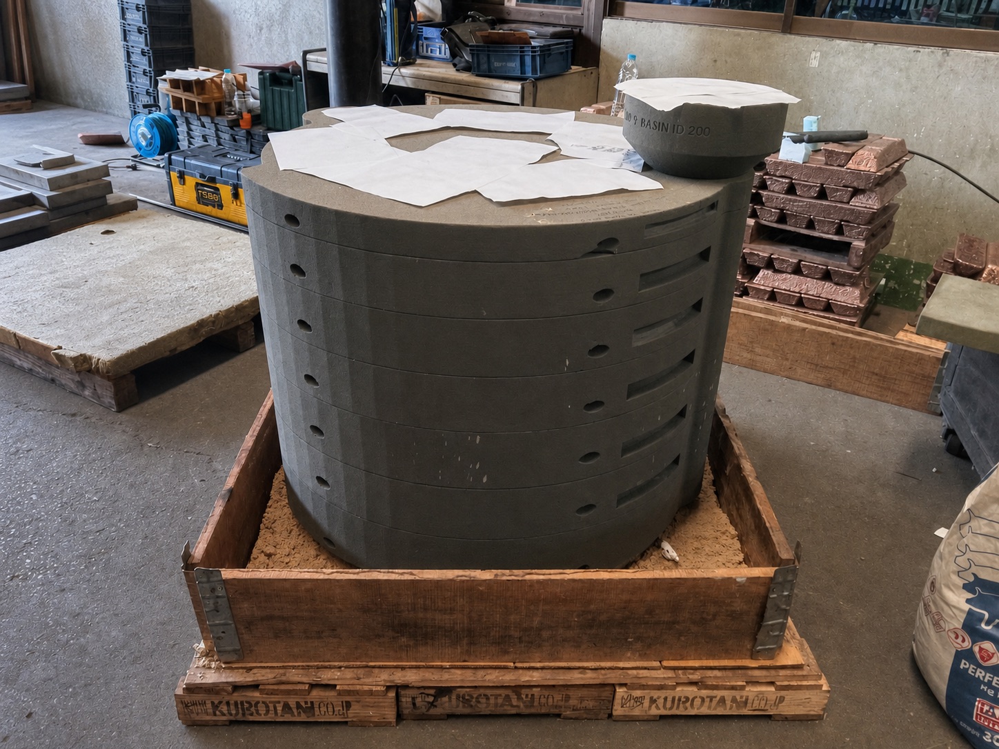
    Assembled 3D-printed sand mold package ready for pouring
    Printed sand mold and core package assembled for casting.
  5. 05

    Metal Casting

    Input
    Assembled mold-and-core package and specified alloy.
    Activity
    Mold assembly, melting, pouring and controlled production.
    Output
    Raw casting.
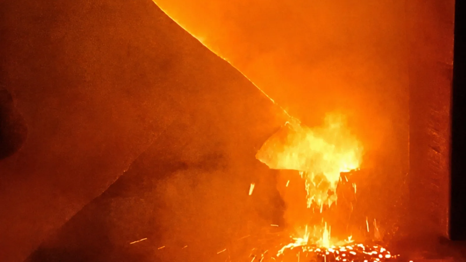
    Molten metal being poured into an assembled sand mold in the foundry
    Pouring into the assembled mold package during coordinated foundry production.
  6. 06

    Finishing and Inspection

    Input
    Raw casting and agreed inspection scope.
    Activity
    Cleaning, finishing, machining coordination and inspection according to project requirements.
    Output
    Inspected component and applicable documentation.
    Dimensional inspection of a finished casting before delivery
    Inspection activities are defined according to the agreed project scope.

Industrial 3D Sand Printing Capability

Confirmed capability of the sand binder jetting system operated by Speed3D Mold
Printing systemExOne S-Max®
Printing processIndustrial sand binder jetting
Build volume1,260 litres
Build dimensions1,800 × 1,000 × 700 mm
Layer height0.2–0.5 mm, depending on material and process settings
Dimensional accuracy±0.5 mm on the printed sand geometry, depending on part size and geometry
Sand and binder systemSilica sand with furan binder
Mold and core applicationsSand molds, complex cores, internal flow passages and one-off or low-volume mold packages
Project data formats commonly receivedSTEP, STP, STL, DWG, DXF and PDF drawings; scan data or a physical component where no CAD exists
Connected casting processesCasting simulation, coordinated metal casting, machining coordination and inspection

Accuracy values refer to the printed sand mold or core. Final casting tolerances also depend on alloy shrinkage, mold design, pouring conditions, heat treatment, finishing and machining requirements. Lead times are project-dependent and confirmed per enquiry; these values are not universal guarantees.

Explore Sand Binder Jetting Technology
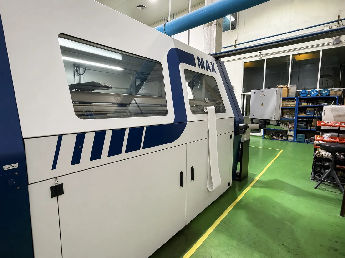
ExOne S-Max industrial sand binder jetting system operated by Speed3D Mold in Thailand
Sand binder jetting system used to produce the mold and core packages.

Manufacturer Reference

Long-Term S-Max Experience

In its LinkedIn feature, ExOne described more than 15 years of S-Max use at Speed 3D Mold and noted that the system remained in production at the time of the post.

View the ExOne Feature

Engineering Checks Before Mold and Core Production

Receiving a CAD file does not automatically mean the geometry is ready for casting.

A printable file is not necessarily a casting-ready design. The geometry must be reviewed in relation to the alloy, filling behaviour, solidification, mold assembly, finishing and inspection requirements.

  • Geometry and casting feasibility
  • Wall thickness and section transitions
  • Shrinkage and machining allowances
  • Core design and core positioning
  • Parting and mold-assembly strategy
  • Gating and feeding concept
  • Print orientation and handling considerations
  • Inspection and documentation requirements

Where 3D Sand Printing Creates Engineering Value

Documented Mold and Core Examples

The photographs below show molds, cores and mold assemblies produced within Speed3D Mold’s documented manufacturing workflow.

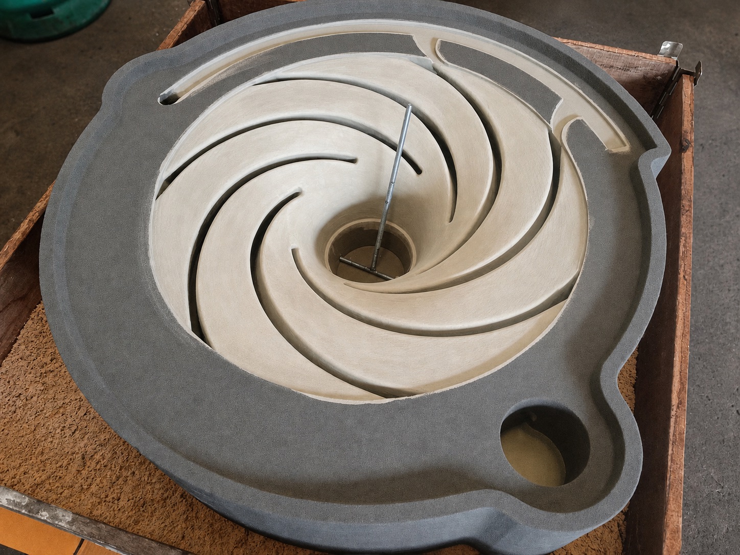
Circular printed sand core seated inside a larger gray sand mold section

Printed Sand Core for a Closed Impeller

The photograph shows a shaped sand core seated within the surrounding printed mold section.
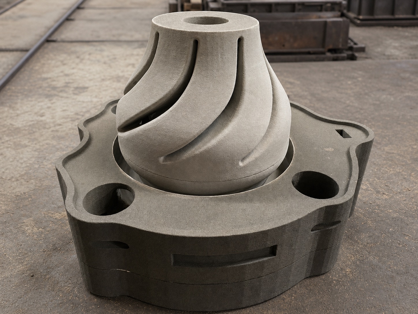
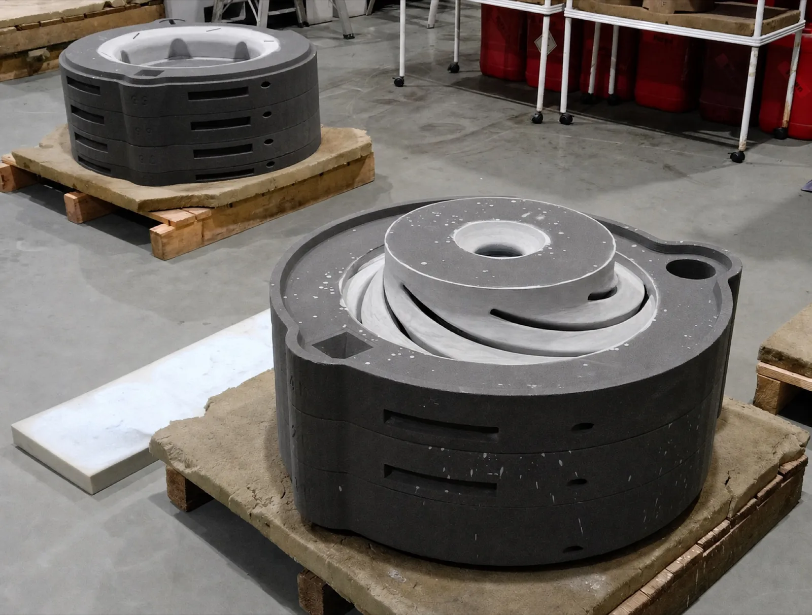
Tall curved-vane sand core positioned on stacked gray mold sections

Printed Sand Core for a Steel Pump Bowl

The photograph shows the printed central core and lower mold sections used in the documented steel pump bowl project.
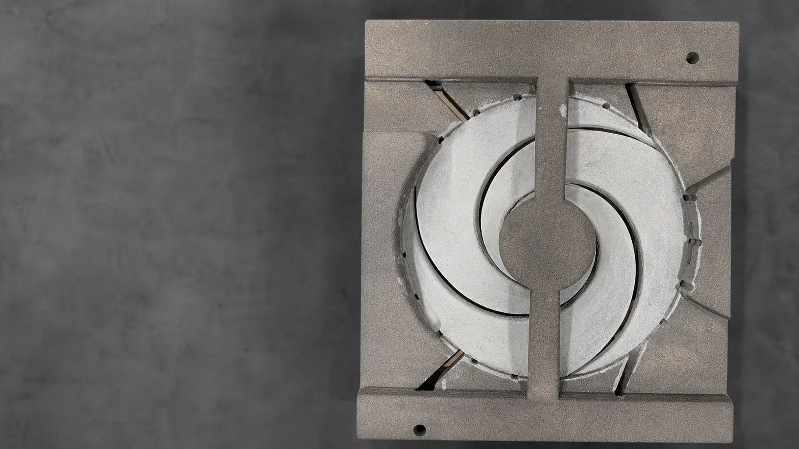
Sectioned rectangular sand mold surrounding a circular impeller-shaped cavity

Printed Sand Mold for an Impeller

The photograph shows a sectioned printed sand mold with a circular impeller cavity and locating features.

Where This Workflow Can Be Applied

Project suitability depends on geometry, quantity, alloy, available data, inspection requirements and delivery schedule.

Complex Mold and Core Geometry

Printed sand may support molds and cores that are difficult to produce using conventional tooling.

Replacement Components Without Existing Tooling

Projects may begin from drawings, CAD data, scan data or an existing component, subject to engineering review.

One-Off and Low-Volume Castings

Patternless production may avoid dedicated tooling where the required quantity does not justify conventional pattern equipment.

New Casting Development

Printed molds and cores can support design iteration before the manufacturing route is finalized.

Urgent Mold-and-Core Requirements

Digital mold and core production may shorten the tooling preparation stage, depending on project complexity and production readiness.

Hybrid Production Routes

Printed cores may be combined with conventional molds when that route is more practical for the component.

Documented Project Evidence

Documented Application: Complex Impeller Mold-and-Core Production

Challenge

Four large double-suction impellers were required as replacements, with the customer needing delivery within six weeks. The enclosed double-suction passages would conventionally require dedicated pattern and core equipment.

Engineering and manufacturing route

Casting design and rigging development, casting simulation, preparation of mold and core data, sand 3D printing of the mold-and-core packages, casting and machining.

Verified result

Reported timings for the double-suction impeller project
ScopeReported time
Mold-and-core productionReported printing timeline for the four mold-and-core packages.Seven days
Casting deliverySeparately reported by ExOne as a further period after mold production.Seven days
MachiningReported subsequent machining period.A further seven days

The reported seven-day period covers production of the four mold-and-core packages. Casting and machining were reported as further separate periods, so the complete finished components were not delivered within seven days.
View the Full Impeller Case Study
3D-printed sand molds produced for four double-suction impeller castings
Printed sand mold-and-core packages for the double-suction impeller project.
Component
Double-suction impeller
Material
Lead-tin bronze
Quantity
Four castings
Diameter
620 mm
Part weight
250 kg each
Mold package
900 mm diameter × 700 mm height
Print volume
650 litres
Customer requirement
Replacement within six weeks
Source
ExOne case study

From Printed Sand to Metal Component

Mold and core production is connected to actual foundry production rather than supplied as a stand-alone printing service. The printed package is assembled, poured and finished within a coordinated casting programme.

Not every alloy is suitable for every geometry or service condition. Material selection is reviewed against the component, application and inspection requirements for each project.
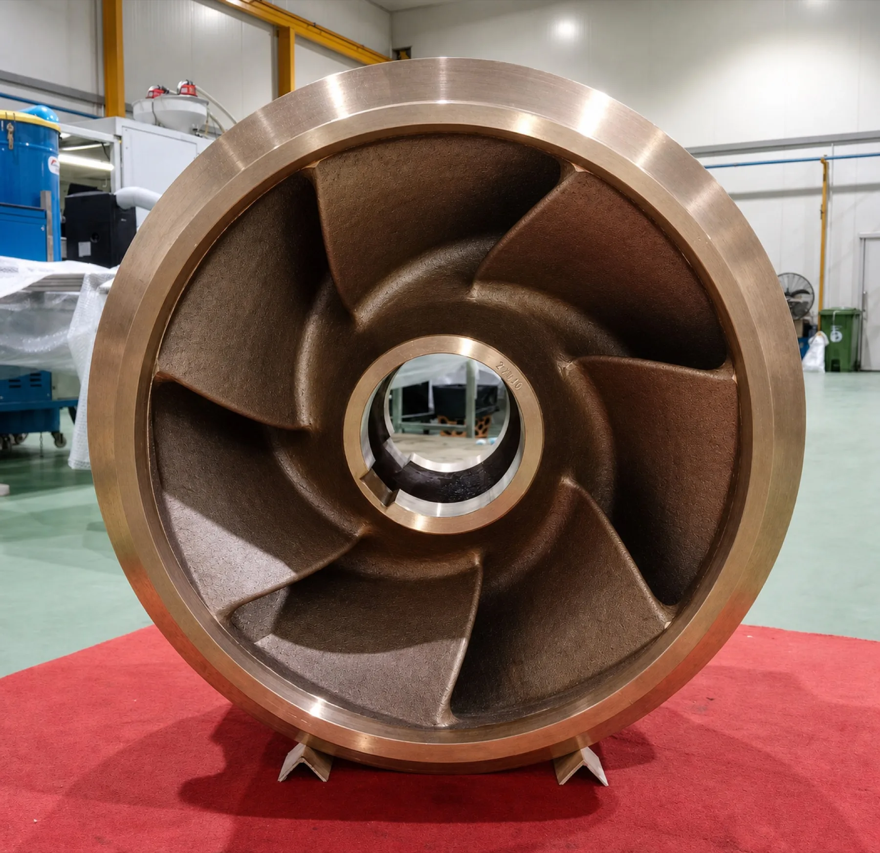
Finished double-suction bronze impeller casting produced from printed sand molds
Cast component produced from the printed mold-and-core package.
  • Aluminium bronze and nickel aluminium bronze

    C95400, C95500 and C95800 grades used for seawater pumps, propellers and shafts.

  • Tin bronze and other copper-based alloys

    C90500 tin bronze, leaded red brass C83600 and related copper alloys.

  • Cast iron and ductile iron

    Gray cast iron and ductile iron grades such as ASTM A48, FCD 450 and ASTM A536.

  • Stainless steel casting alloys

    Austenitic grades ASTM A351 CF8 and CF8M, and martensitic ASTM A743 CA6NM.

Inspection Defined Around the Project Requirement

Inspection methods, acceptance criteria and documentation scope must be agreed before production.
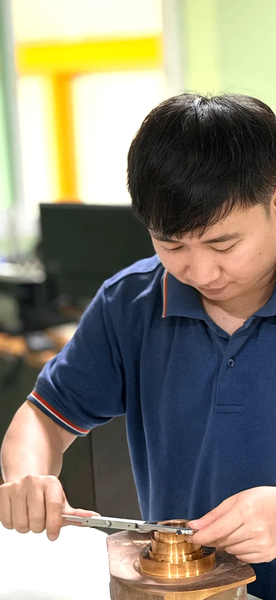
Technician measuring a manufactured component during dimensional inspection
Dimensional verification performed on a manufactured component according to the agreed project scope.
  • Dimensional inspection

    Measurement of agreed dimensions and interfaces against the project requirement.

  • 3D scan comparison

    Comparison of scan data against the reference geometry where this is part of the agreed scope.

  • Material verification

    Chemical composition verification for the specified alloy, where required by the project.

  • Visual inspection

    Surface and general condition review of the casting after finishing.

  • Machining inspection

    Verification of machined features where machining is coordinated as part of the scope.

  • Project-specific testing or documentation

    Additional testing or records may be applied where agreed before production.

Plan the Right Manufacturing Route

Share the project information currently available. Speed3D Mold will review the component, production requirement and technical constraints to determine whether 3D sand printing, conventional tooling or a hybrid manufacturing route is more appropriate.

Project InformationEngineering ReviewRecommended Manufacturing Route
What You Can Share

Available Project Information

Partial information is enough to begin. Missing details can be identified during the engineering review.

  • Drawing, CAD file, scan data or physical sample
  • Component dimensions and approximate weight
  • Required alloy or service environment
  • Required quantity
  • Machining requirements
  • Inspection or certification requirements
  • Target delivery date
  • Photographs of the existing component
  • Known wear, damage or performance problem
What We Evaluate

Engineering and Production Factors

The manufacturing route is selected according to the complete project requirement—not by the printing process alone.

  • Geometry and casting feasibility
  • Mold, core and assembly strategy
  • Component size and handling requirements
  • Material and process compatibility
  • Quantity and expected repeat demand
  • Surface finish and dimensional requirements
  • Tooling availability
  • Inspection and documentation scope
  • Required schedule and production readiness

The Outcome of the Review

Based on the available project information, Speed3D Mold may recommend printed sand molds and cores, conventional tooling, a hybrid route, or further engineering work before production. The appropriate route depends on the component and project requirements.

3D Sand PrintingConventional ToolingHybrid ManufacturingFurther Engineering Review
Compare 3D Sand Printing with Traditional Patterns

You do not need to have every item prepared before contacting us.

Conference Presentation

AFC 2023: Printed Moulds for New and Replacement Cast Components

At the 16th Asian Foundry Congress, Speed3D Mold presented its experience of using 3D sand printing to produce moulds for new and replacement cast components, including selected spherical feeder and helical sprue gating examples.

View AFC 2023 Presentation

Frequently Asked Technical Questions

Does Speed3D Mold print the final metal part?
No. The binder-jetting process produces the sand molds and cores. The printed mold package is then used in the metal casting process to produce the component in the specified alloy.
Can a project start without an original CAD file?
Yes. A project can start from drawings, scan data, or an existing physical component. Where usable CAD data does not exist, the geometry is captured and reconstructed first through reverse engineering, subject to the condition of the reference component.
When is 3D sand printing preferable to conventional tooling?
It is generally most relevant for one-off or low-volume work, complex core packages and projects where no pattern exists. The comparison is project-dependent and is made against geometry, quantity, material, tolerance, inspection requirements and schedule.
Can printed sand molds be used for replacement castings?
Yes, where the replacement geometry can be established from drawings, scan data or an existing component and reviewed for castability. Documented replacement work using printed molds is described in the case studies and published technical work referenced on this site.
What determines mold and core lead time?
The condition of the available project data, the engineering review, mold and core complexity, the size of the mold package relative to the build volume and the current production schedule. Lead time is confirmed per project rather than stated as a general figure.
Can Speed3D Mold provide casting simulation and metal casting?
Yes. Casting simulation is applied where required for the project, and metal casting, machining coordination and inspection are carried out as part of the agreed scope rather than as separate print-only supply.
What information is required for a quotation?
A drawing, CAD file, scan data or photographs of the component, principal dimensions and approximate weight, the required alloy, quantity, machining scope, inspection requirements and the target delivery date.
Is 3D sand printing suitable for repeat production?
It can be used for repeat work, but for stable, higher-volume repeat production conventional or hybrid tooling may be more economical. The route is evaluated against the complete project requirement.

Discuss the Right Manufacturing Route for Your Casting

Share your drawing, CAD data, scan data or existing component. Our engineering team will review whether 3D sand printing, conventional tooling or a hybrid route is appropriate for the project.

View Engineering Case Studies

Technology Representation

ExOne logo

ExOne Sales Representative in Thailand

Speed 3D Mold Co., Ltd. is listed by ExOne as a sales representative in Thailand, supporting local coordination for industrial sand 3D-printing solutions.

Verify our listing on ExOne’s official global support network.

View Official ExOne Listing


MEMBERS & SOCIETIES

Thai Foundry Association
FTI