Reverse Engineering for Replacement Cast Components
Start with the component that still exists. Where drawings, CAD data or original tooling are missing or no longer reliable, the physical part can provide the starting point for engineering reconstruction and a replacement casting.
Not every damaged component can be reconstructed. The available evidence has to be reviewed first.
When the Physical Component Is the Best Available Engineering Reference
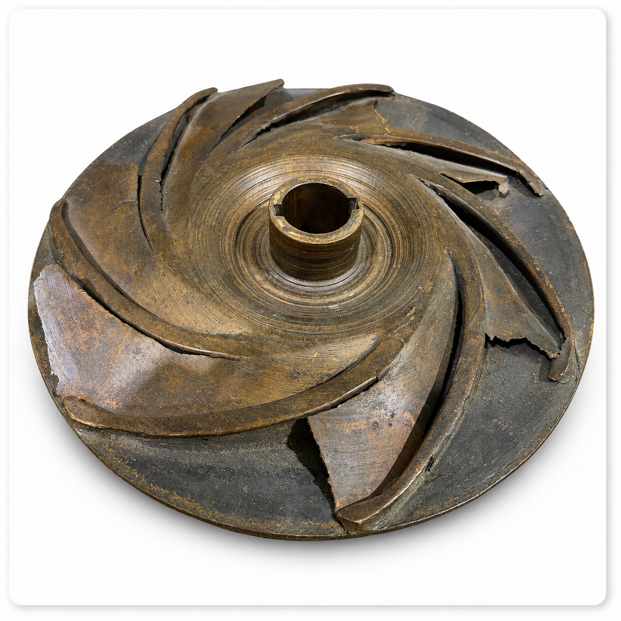
Replacement work on installed equipment rarely begins with complete engineering data. The component is usually still present, but the documentation that defined it is not. In that situation the part itself becomes the reference — with the important qualification that the part in front of you is the worn part, not the designed part.
- Original drawings were never archived or cannot be located.
- Drawings exist but no longer match the component actually installed.
- Original CAD data was lost with a previous supplier or design office.
- The casting pattern or tooling no longer exists or is unusable.
- OEM support for the equipment has been discontinued.
- The component is worn, corroded, cracked or partially broken.
- Only one or a few replacements are required, so new tooling is hard to justify.
- The physical component is the only remaining reliable engineering reference.
Measurement Is Only the Starting Point
3D scanning is dimensional capture. It records the component in the condition it is in today. Reverse engineering is the engineering work that follows: interpreting that measurement, reconstructing the geometry the component is supposed to have, and defining how it will be manufactured.
Scan data of a service-run casting typically contains wear, corrosion, impact damage, deformation and surface irregularity. A replacement model that reproduces every measured surface would reproduce the condition that made the part unusable.
Equipment and scanning methods are described separately on the 3D scanning page.
Reconstructing Geometry Is Not the Same as Copying Wear
Reconstruction is an engineering judgement about which measured geometry represents the design and which represents service damage. That judgement is built from several sources of evidence rather than from the scan alone.
Surviving geometry
Areas that have not been eroded or deformed carry the most reliable dimensional information.
Symmetry and repetition
Repeated features such as blades, bolt patterns and vanes can be cross-compared against each other.
Functional interfaces
Bores, bearing seats, sealing faces and mounting flanges define how the part must fit.
Mating components
Adjacent parts and assembly data constrain envelope and interface dimensions.
Available documentation
Partial drawings, nameplates, catalogues or inspection records are used where they exist.
Manufacturing requirements
Casting and machining requirements are considered so the model can actually be produced.
The available evidence must be reviewed before determining whether a reliable replacement geometry can be reconstructed. Reverse engineering recovers a defensible engineering definition from the evidence that survives; it does not recover the original design records.
From Physical Component to Manufacturing-Ready Data
Each stage has a defined input, engineering activity and output. Not every project runs through all nine stages — the route depends on the evidence available and on whether Speed3D Mold also produces the casting.
Existing Component Assessment
- Input
- Physical component, photographs, any available drawings or history.
- Activity
- Review of wear, damage and remaining reference surfaces to judge whether a reliable replacement geometry can be reconstructed.
- Output
- Engineering assessment of feasibility and missing information.
Dimensional Capture
- Input
- Component in its current condition.
- Activity
- 3D scanning and measurement to record the as-found geometry.
- Output
- Measured geometry data of the part as it exists today.
Engineering Interpretation
- Input
- Measured data plus any supporting documentation.
- Activity
- Separating design geometry from wear, corrosion and deformation; deciding which measured surfaces should be reproduced and which should not.
- Output
- Agreed basis for reconstruction and a list of open assumptions.
CAD Reconstruction
- Input
- Interpreted geometry and functional datums.
- Activity
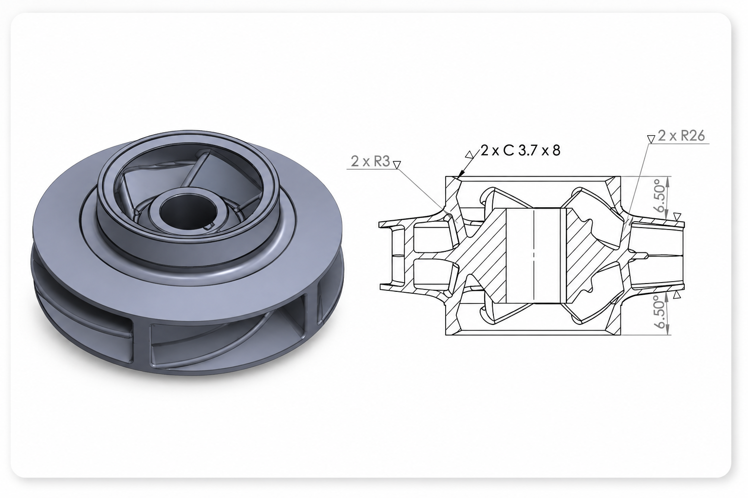
- Rebuilding the component as a CAD model referenced to functional faces rather than to arbitrary scan axes.
- Output
- Reconstructed 3D model and dimensioned drawing.
Casting and Manufacturing Review
- Input
- Reconstructed model.
- Activity
- Review of wall sections, machining stock, draft, core strategy and mould layout so the model becomes a casting definition.
- Output
- Casting-ready geometry with rigging and machining allowances.
Casting Simulation
- Input
- Casting geometry, rigging layout and alloy data.
- Activity
- Review of filling, solidification and feeding behaviour to identify areas requiring engineering attention before production.
- Output
- Simulation review and, where required, revised rigging.
Digital Mould and Core Production
- Input
- Approved mould and core geometry.
- Activity
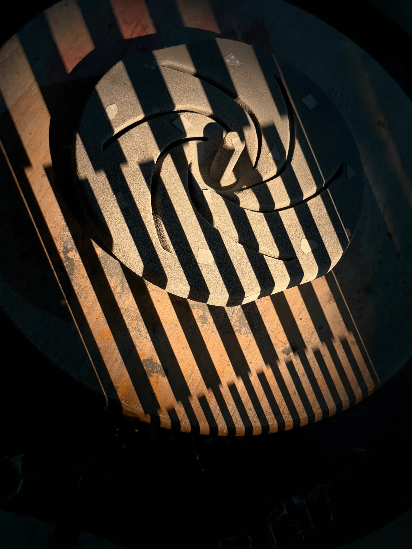
- 3D sand printing of moulds and cores directly from the digital data, without a conventional pattern.
- Output
- Printed sand mould and core package.
Casting
- Input
- Assembled mould package and specified alloy.
- Activity
- Melting, pouring, cooling, fettling and heat treatment as required by the specification.
- Output
- As-cast replacement component.
Dimensional Verification
- Input
- Manufactured component and reconstructed CAD.
- Activity
- Comparison of the produced part against the engineering data used to make it.
- Output
- Dimensional comparison and inspection records.
Engineering the Replacement, Not Just the CAD Model
A model that matches the reconstructed shape is not yet something a foundry can produce. Between reconstruction and manufacture, the geometry has to be converted into a casting definition. This is where reverse engineering connects directly to replacement casting of obsolete components.
- Cast geometry separated from machined geometry, so machining stock is placed where it is needed.
- Machining interfaces and datum faces defined for the workshop that will finish the part.
- Mould and core strategy considered together with the reconstructed shape.
- Casting allowances applied for shrinkage and process behaviour of the specified alloy.
- Manufacturability reviewed before mould data is released.
- Inspection references defined so the finished part can be compared back to the model.
Reverse Engineering Worn Pump Components
Pump wet-end components are a common reverse engineering case because they wear in service, are often older than their documentation, and have geometry that cannot be recovered by hand measurement.
- The pump is obsolete and no longer supported by the original manufacturer.
- The impeller is worn or cavitation damaged, so the measured surface is not the design surface.
- No original drawing or CAD model is available for the wet-end components.
- The casting pattern for the impeller or bowl no longer exists.
- Blade and passage geometry is too complex for hand measurement alone.
- Only one or two replacements are needed, so dedicated tooling is difficult to justify.
Documented Reverse Engineering: Vertical Pump Impeller
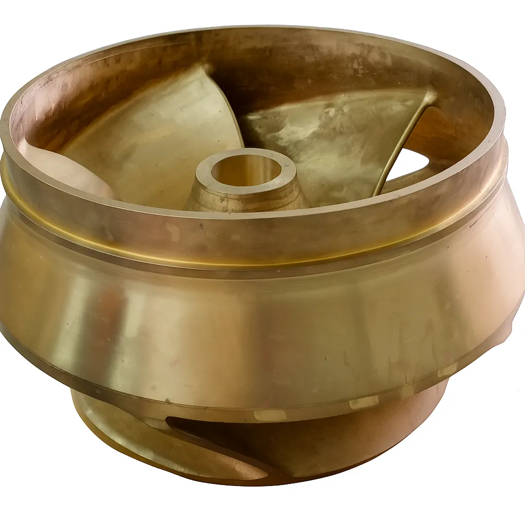
The original impeller was cracked and corrosion damaged, and the replacement had to fit the existing pump body and adjacent components. The documented route was 3D scanning of the damaged impeller, CAD reconstruction, sand moulds produced by binder jetting, then casting and dynamic balancing.
- Component
- Vertical pump impeller
- Diameter
- 1,270 mm
- Weight
- 900 kg
- Material
- ASTM B148-C95500 aluminium bronze
- Reference condition
- Cracked and corrosion damaged
- Production time
- 4 weeks
From Physical Propeller to Replacement Casting
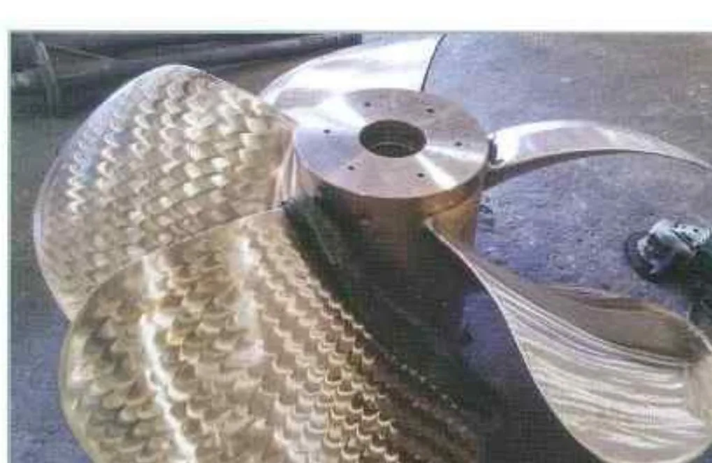
A damaged patrol-vessel propeller was replaced with no original pattern available. The documented workflow included 3D scanning, CAD reconstruction and engineering review, casting simulation, a 26-section binder-jet printed sand mould, casting, finishing and dynamic balancing. This shows the workflow is not limited to pump impellers.
- Component
- Patrol vessel propeller
- Diameter
- 1,200 mm
- Weight
- 650 kg
- Material
- ASTM B148-C95800 nickel aluminium bronze
- Reference condition
- Damaged physical propeller
- Mould system
- 26 printed sand sections
These are documented projects, not a statement of what is possible for every component. Feasibility for a new part is determined by engineering review of the evidence available for that part.
Reconstructed Geometry Still Has to Be Cast
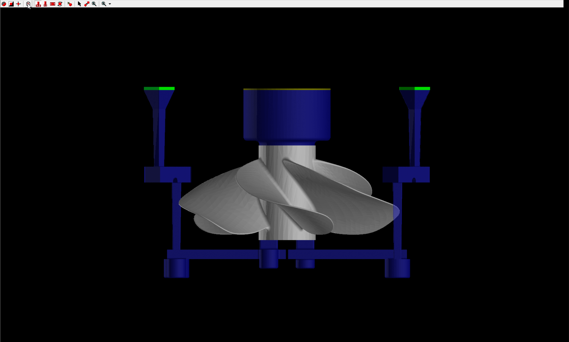
The digital model and the casting process are decided together. Filling behaviour, solidification and feeding depend on the reconstructed wall sections and on the rigging chosen for them, so the model and the process are reviewed as one problem rather than in sequence.
Simulation is used to identify areas of casting risk that warrant engineering attention before production. It supports the decision; it does not guarantee a defect-free casting.
Casting simulation for replacement componentsWhen the Original Pattern No Longer Exists
Reconstructed CAD can be used to print sand moulds and cores directly, and the casting is produced from that printed package. The pattern step that would normally sit between the drawing and the mould is not required.
This route is often relevant for obsolete components, one-off replacements, low quantities, complex internal geometry and cases where the original tooling is missing. Whether it is the right route for a given part depends on geometry, alloy and quantity; it is not automatically faster or cheaper than a conventional pattern.
Patternless manufacturing and 3D sand printing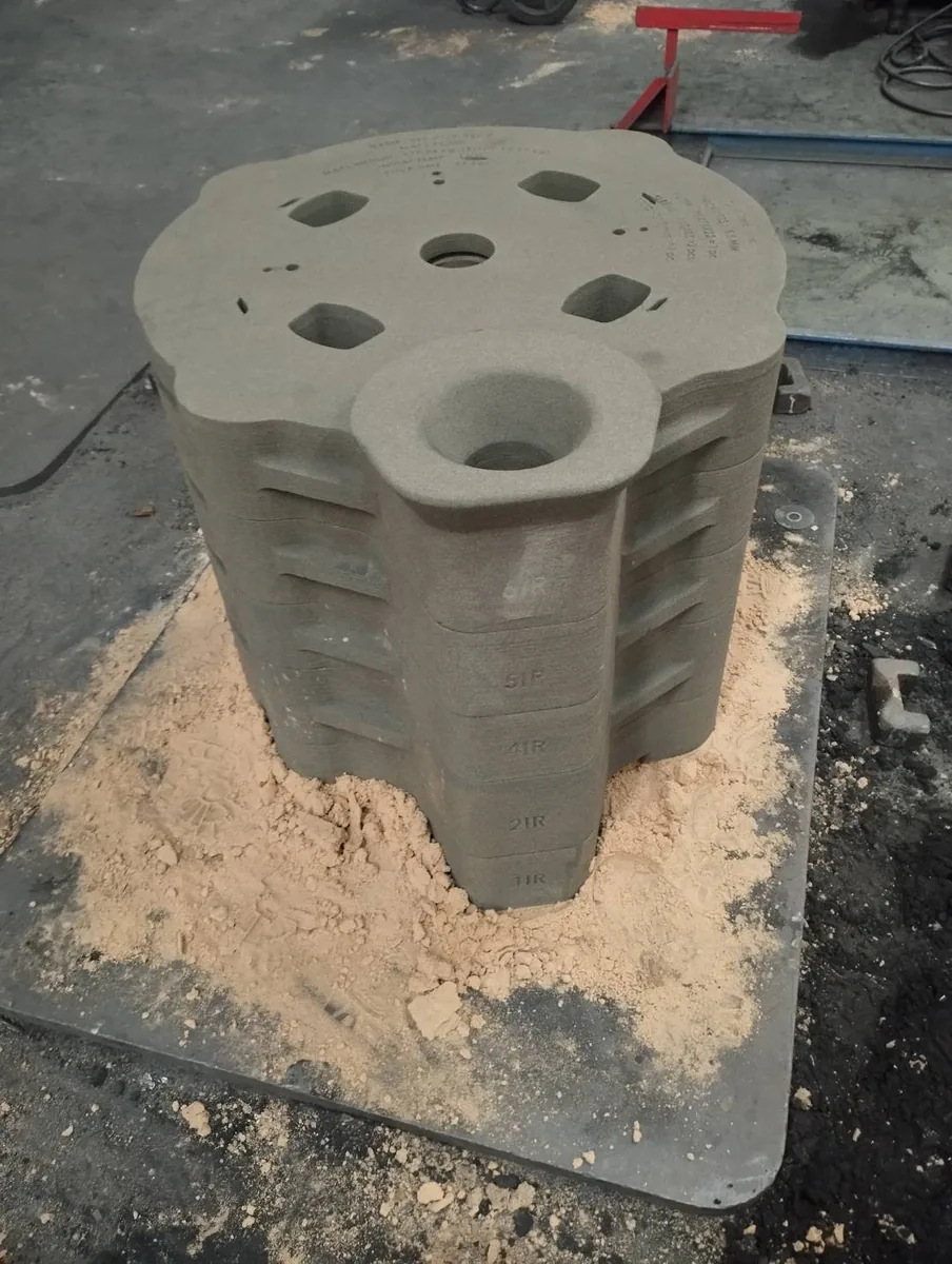
Compare the Manufactured Result Back to Engineering Data
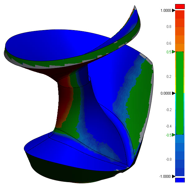
Reverse engineering produces the data set the part is made from, so that same data set is the reference for checking it. Scan-to-CAD comparison is used to compare a legacy component against the reconstructed model, and to compare the manufactured component against the model that defined it.
Comparison scope and inspection requirements are agreed per project rather than applied as a fixed standard.
CAD verification and dimensional comparisonWhat Information Helps Start a Project
Not all of this is required, but each item reduces the number of assumptions the reconstruction has to make.
- The existing physical component, if it can be released
- Photographs of the component, including damaged areas
- Any drawings, sketches or nameplate data available
- Previous CAD data, even if incomplete or unverified
- Known or suspected material specification
- Overall dimensions and critical interface dimensions
- Information on mating components and assembly
- Required quantity
- Application and operating conditions
- Known failure or wear condition
- Inspection or documentation requirements
Project feasibility depends on the evidence available and on engineering review of that evidence.
When Reverse Engineering May Not Be Enough
Some components cannot be defined from the physical part alone. In these cases additional information, testing or design work is required before a replacement can responsibly be produced.
- Critical geometry is completely destroyed and no equivalent reference remains.
- No undamaged reference surfaces or datums survive on the component.
- Operating duty, loading or service conditions are unknown.
- The material cannot be established from documentation or analysis.
- Design information for a safety-critical function is missing.
- A reconstruction would depend on assumptions that cannot be supported by evidence.
Related Engineering Evidence
Pump Replacement Casting Engineering
Engineering pillar for impellers, bowls and casings in pump equipment.
Replacement Casting
Producing obsolete and hard-to-source cast components.
Casting Without Original Drawings
What evidence is needed when documentation is missing.
3D Scanning
Dimensional capture of existing components.
Casting Simulation
Reviewing filling and solidification before production.
Patternless Manufacturing
Sand moulds and cores printed directly from CAD.
CAD Verification
Comparing physical parts against engineering data.
Impellers
Impeller geometry, materials and production routes.
Research: 3D Sand Printing for Part Replacement
Published work on replacement components without original tooling.
Technology Representation

ExOne Sales Representative in Thailand
Speed 3D Mold Co., Ltd. is listed by ExOne as a sales representative in Thailand, supporting local coordination for industrial sand 3D-printing solutions.
Verify our listing on ExOne’s official global support network.
View Official ExOne ListingMEMBERS & SOCIETIES


Key Takeaways
- Where documentation is missing, the surviving physical component is often the most reliable engineering reference available.
- Measurement is the input; reverse engineering is the interpretation and reconstruction that follows it.
- A scan of a worn part records wear, so a replacement model should not automatically reproduce every measured surface.
- A geometrically correct model is not yet a casting definition — manufacturing requirements have to be added before production.
- Feasibility depends on the evidence available, and some components will require additional information before a replacement can be defined.
Frequently Asked Questions
Have an Obsolete or Damaged Cast Component?
Send whatever evidence you have and our engineers will review whether a reliable replacement geometry can be reconstructed: photographs, the existing component, drawings if available, dimensions, material information, quantity and application details.