
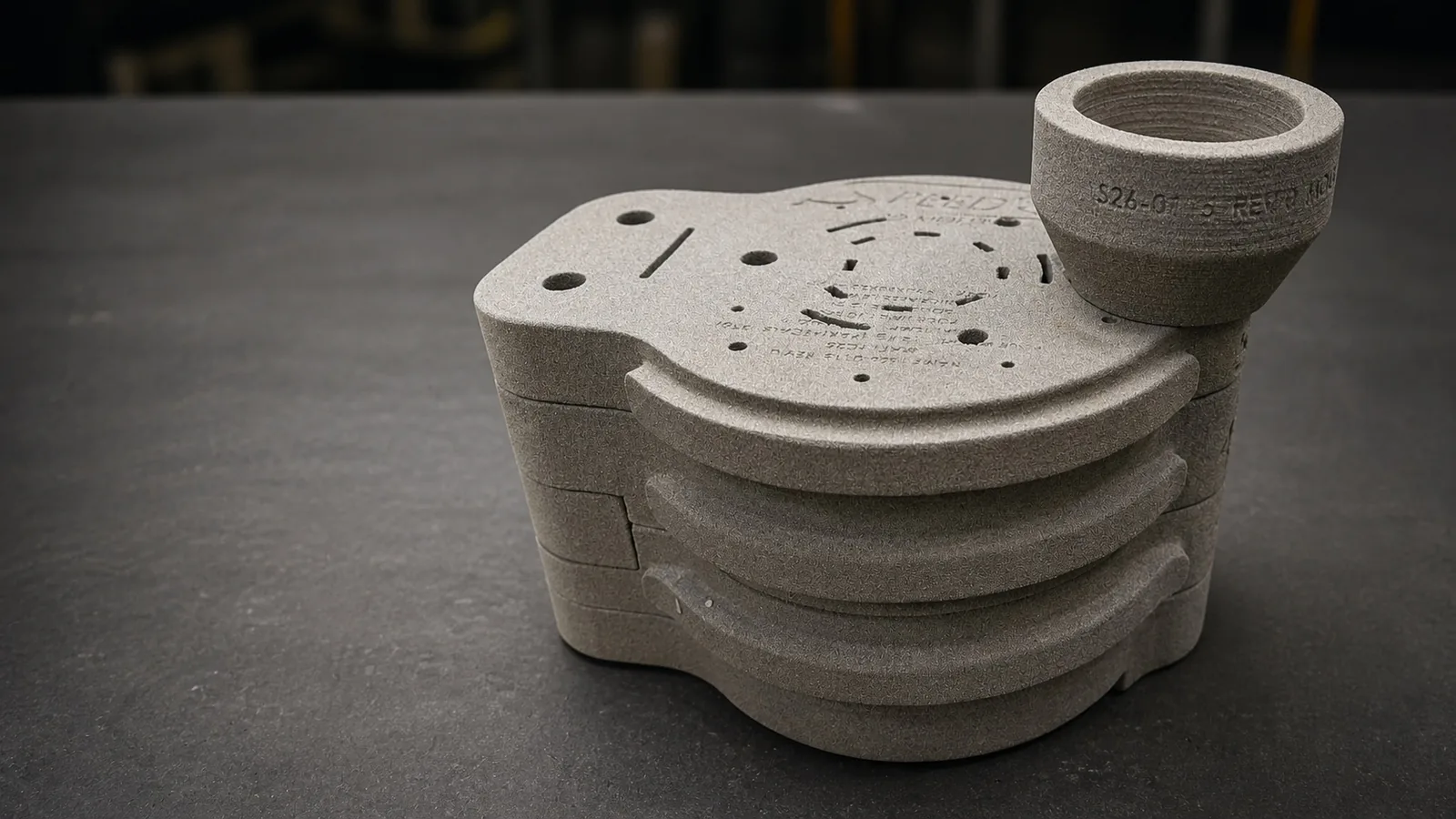
What is being compared?
- Directly printed sand moulds
- Mould sections produced layer by layer from bonded sand using prepared digital data, without a physical pattern.
- Directly printed sand cores
- Cores forming internal casting geometry, printed directly instead of being made in a core box.
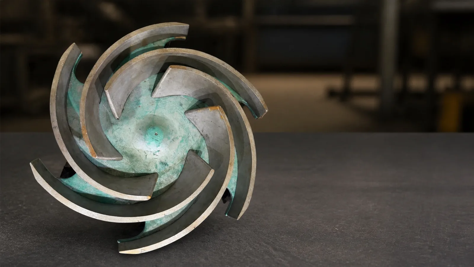
- Traditional wooden patterns and core boxes
- Reusable physical tooling used to form mould cavities and cores in a conventional sand-moulding workflow.
- Hybrid moulding
- Conventional moulding combined with printed cores or printed mould sections where geometry justifies it.[2]
Key differences at a glance
Short answers to the questions most often raised during process selection, each applying to a set of engineering conditions rather than to every project.
What is the difference between 3D sand printing and traditional patterns?
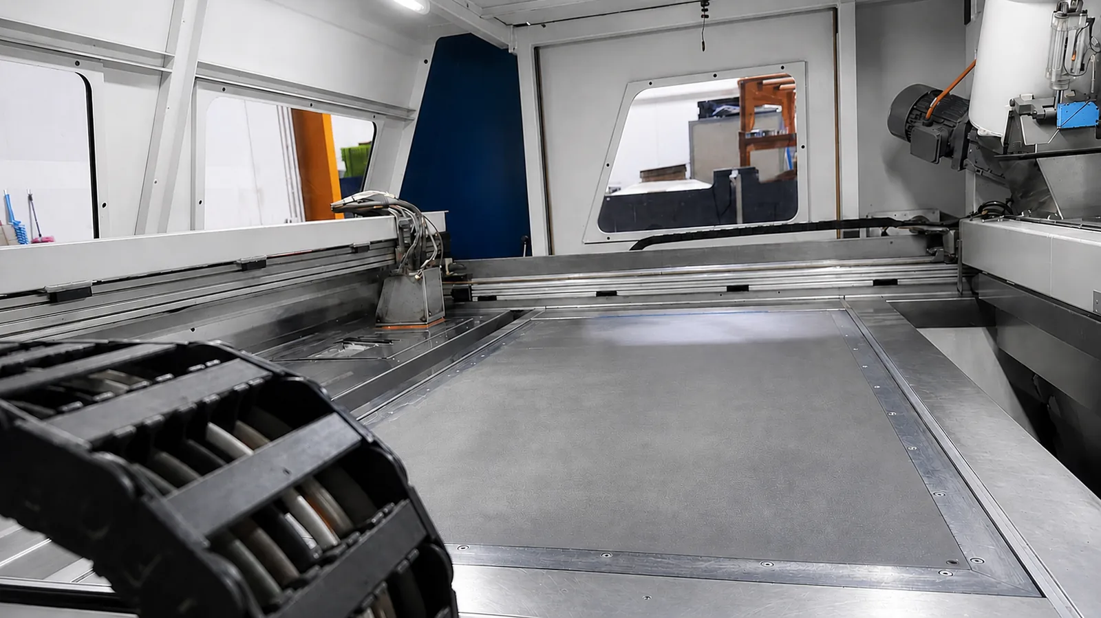
3D sand printing (binder jetting) builds mould and core sections layer by layer directly from digital data, so no physical pattern or core box is manufactured. Traditional pattern making produces reusable tooling that forms the mould cavity repeatedly. Both routes feed the same downstream foundry operations.
When should manufacturers choose patternless manufacturing?
Patternless manufacturing is advantageous when tooling cost, development speed or design flexibility dominate the project constraints — typically prototypes, low volumes, urgent replacement parts without surviving tooling, or geometry with complex internal passages.
When are traditional patterns still preferable?
Traditional patterns remain preferable when a stable design is produced repeatedly over a period long enough for the tooling to be amortised and maintained economically, and when the geometry releases from a conventional parting arrangement.
Which process is better for prototypes?
For prototypes and first articles, 3D sand printing is usually the more appropriate route, because tooling produced for a single mould cannot be amortised and its manufacture extends the schedule.
Which process is better for series production?
For stable series production, traditional pattern equipment is usually more economical, because the tooling cost is distributed across many moulds while printing cost recurs with every build.
Which process is better when engineering changes are expected?
Where revisions are expected, a digital workflow carries lower change cost: the geometry is updated in CAD rather than by reworking or replacing physical tooling. Engineering review and reprinting are still required for each revision.
Three principles before comparing the processes
Tooling cost is not total project cost
Tooling is one line in a workflow that also includes engineering preparation, mould and core production, gating and feeding design, pouring, fettling, machining, inspection and rework risk. A process that avoids tooling can still carry a higher total cost.
Printer build time is not time to finished casting
A printed mould still has to be depowdered, cleaned, coated, assembled, poured, fettled, machined and inspected. Comparisons should be made against the complete route to the first accepted casting.
Production quantity must be evaluated together with geometry and design stability
Quantity alone does not decide the route. A large batch of a design that is still changing, or a small batch of a geometry with severe core complexity, can reverse the expected conclusion.
Engineering trade-off comparison
Neither route is superior in general. Each column describes the conditions under which that route carries the engineering advantage.
| Criterion | 3D sand printing (patternless) | Traditional pattern making |
|---|---|---|
| Physical tooling | Not required when the mould or core is printed directly | Pattern and core-box tooling must be designed, manufactured and maintained |
| Lead time to first casting | Tooling manufacture is removed, but engineering preparation, printing, finishing and downstream foundry stages remain | Tooling manufacture is an additional front-end stage before the first mould can be produced |
| Unit cost behaviour | Printing and finishing cost recurs with every build, so unit cost changes little with quantity | Tooling is a one-time cost distributed across the moulds produced, so unit cost falls as quantity rises |
| Total project cost | Usually favourable where quantity is limited or tooling would be used only once | Usually favourable where a stable design is produced repeatedly over the tooling's usable life |
| Design flexibility | Geometry is defined digitally, including features that are difficult to release from a conventional parting arrangement | Geometry must respect draft, parting and pattern-release constraints |
| Engineering changes | Revisions are made to the digital data; engineering review and reprinting are still required | Revisions may require modification or replacement of the pattern or core box |
| Core complexity | Complex internal passages can be printed as a single core package, reducing core-box tooling and assembly steps | Complex internal geometry may require multi-part core boxes and manual core assembly |
| Production volume | Suited to prototypes, one-off parts and low-volume batches | Suited to medium and high-volume repeat production |
| Repeatability | Repeatability depends on print data control, printer condition and finishing discipline | Repeatability derives from reusable tooling maintained in a controlled condition |
| Engineering risk | Risk concentrates in geometry preparation, mould segmentation and build utilisation | Risk concentrates in tooling accuracy, pattern wear and the cost of late design change |
Engineering decision matrix
A condensed reading of the trade-offs above. Each row states the typical engineering direction for a common project situation.
| Situation | Process to evaluate | Engineering reason |
|---|---|---|
| Prototype development | 3D sand printing | Tooling used once cannot be amortised and extends the schedule. |
| Low-volume production | 3D sand printing | Recurring print cost is normally below an unrecovered tooling investment. |
| High-volume production | Traditional pattern | Tooling cost is distributed across many moulds, lowering unit cost. |
| Existing tooling available | Traditional pattern | The tooling investment has already been made and remains usable. |
| Frequent design revisions | 3D sand printing | Revisions are made in CAD instead of reworking physical tooling. |
| Complex cores | 3D sand printing or hybrid | Printed core packages reduce multi-part core boxes and manual assembly. |
| Urgent replacement part | 3D sand printing | Removes pattern manufacture from the front end when no tooling survives. |
| Stable long-term production | Traditional pattern | Reusable tooling is evaluated on lifecycle unit cost, not first-article speed. |
When to choose 3D sand printing
Patternless manufacturing is advantageous when tooling cost, development speed or design flexibility dominate the project constraints.
Process-selection flow
- Need a casting
- Prototype or low-volume production?Yes 3D sand printing
- Existing usable pattern already available?Yes Traditional pattern
- Complex internal geometry or core package?Yes 3D sand printing
- High-volume, stable repeat production?Yes Traditional pattern
- Engineering review required
Indicative only. Final process selection should always consider geometry, production quantity, schedule, tooling economics and engineering requirements.
Engineering perspective
- Prototype and first-article development — tooling used once cannot be amortised
- Low-volume or one-off production — no tooling investment to recover
- Complex internal geometry — printed core packages replace multi-part core boxes
- Urgent replacement parts — pattern manufacture removed from the front end
- Frequent engineering revisions — changes made in the digital model, not in tooling
When traditional patterns are better
Reusable tooling remains the more economical route when production volume and design stability allow the tooling investment to be recovered.
Engineering perspective
- Medium and high-volume production — tooling cost distributed across many moulds
- Stable, released designs — no change cost against physical tooling
- Existing usable tooling — the tooling investment is already made
- Lowest long-term unit cost — lifecycle unit cost outweighs first-article speed
- Conventional, releasable geometry — conventional parting is not a limiting constraint
Engineering note: these conditions are indicative. Quantity, geometry, schedule and tooling economics are assessed together, because one dominant constraint can reverse the expected conclusion.
What actually drives total project cost?
A professional comparison should account for every activity that consumes engineering time, foundry capacity or material — not only the price of tooling or of a printed mould.[1]
| Cost factor | 3D sand printing | Traditional pattern making |
|---|---|---|
| Physical tooling | A physical pattern or core box may not be required for directly printed moulds or cores | Pattern and core-box tooling normally must be designed and manufactured |
| Engineering preparation | Requires suitable digital geometry, mould segmentation and casting-system preparation | Requires pattern design, allowances, parting strategy and tooling preparation |
| Recurring mould cost | Printing and finishing costs recur with each build | Tooling cost can be distributed across repeated production |
| Design revisions | Digital files can be revised without rebuilding conventional tooling, although engineering and reprinting are still required | A revision may require modification or replacement of the pattern or core box |
| Complex internal geometry | Printed cores can reduce tooling constraints for certain geometries | Complex core boxes and core assembly may be required |
| Storage | Digital manufacturing data must be controlled and maintained | Physical tooling requires storage, identification and maintenance |
| Repeat production | Must be assessed against recurring printing cost and capacity | Can become more attractive when the design is stable and demand repeats |
| Post-processing | Depowdering, cleaning, coating and assembly may be required | Moulding, core making, coating and assembly may be required |
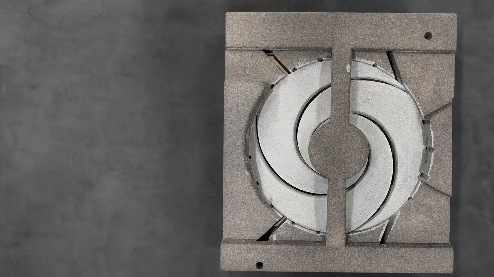
Compare lead time correctly
Compare the complete route to the first accepted casting, stage by stage. Removing tooling shortens one stage only; printer build time is not delivery time.
- Engineering and data review
- Geometry reconstruction or CAD preparation
- Casting-system design and simulation, if required
- Pattern or print-data preparation
- Pattern/core-box manufacturing or sand printing
- Mould/core finishing and assembly
- Pouring schedule
- Fettling and heat treatment, where applicable
- Machining
- Inspection and documentation
Published comparisons report differences in preparation and production effort, but the results are specific to the components, equipment and foundry conditions studied[1][3] and are not transferable delivery times.
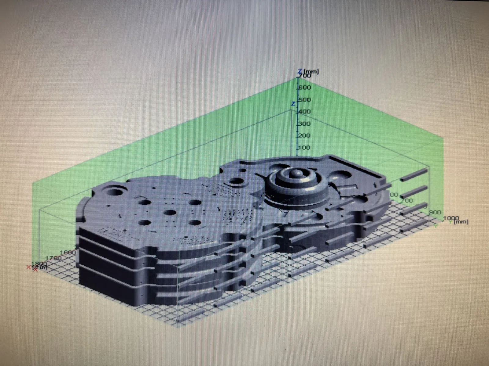
Why there is no universal break-even quantity
A simplified way to frame the comparison, where Q is the required production quantity:
Ctraditional(Q) = Ctooling + Q × (Cmould + Ccasting)
C3DSP(Q) = Q × (Cprinting + Cfinishing + Ccasting)
Simplified decision models, not quotation formulas: they exclude engineering iteration, capacity constraints, rework and other project costs.
The crossing point moves with:
Engineering note: no fixed unit quantity is published. Any threshold quoted without its geometry, material, build-utilisation and tooling assumptions is not transferable to another component.
Process-selection matrix
An initial selection guide — not a substitute for a project-specific engineering assessment.
| Project condition | Process direction to evaluate |
|---|---|
| Replacement part with no surviving tooling | Evaluate reverse engineering followed by a directly printed mould or core |
| Low-volume or one-off requirement | Compare 3D sand printing against the full cost of new tooling |
| Complex internal passages | Evaluate printed cores or a fully printed mould-and-core system |
| Simple external mould with a complex core | Evaluate a hybrid approach |
| Stable design with regular repeat production | Compare reusable traditional tooling against recurring printing cost |
| Design is expected to change | Consider the cost and schedule risk of modifying physical tooling |
| CAD data is unavailable | Engineering preparation or reverse engineering is required before either route |
| Delivery is urgent | Compare the complete route to the first accepted casting, not only mould-production time |
| Future quantities are uncertain | Evaluate initial tooling exposure and the cost of each repeat order |
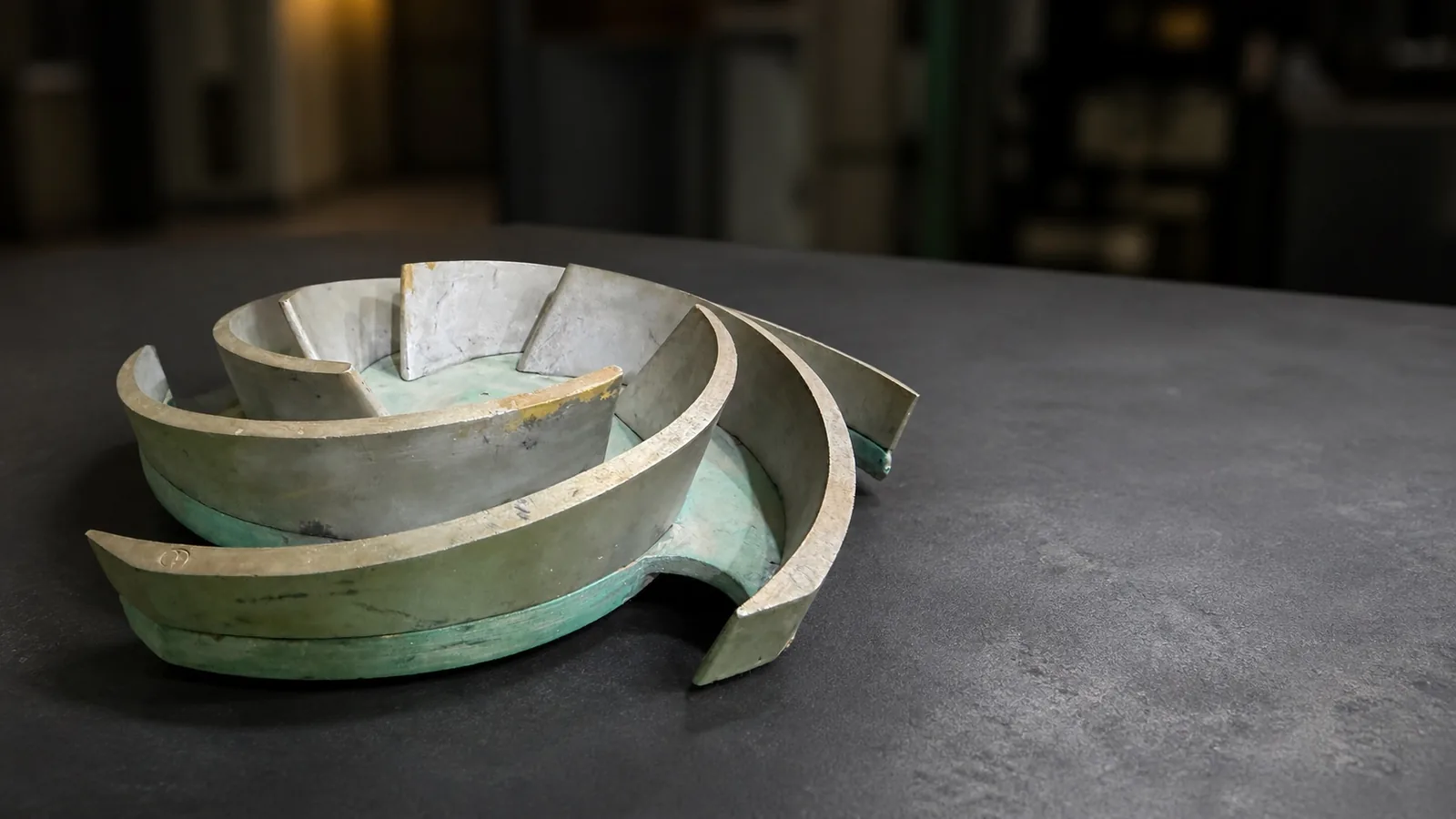
Where no tooling survives, the route usually begins with reverse engineering of the existing component before any moulding decision can be made, and continues through replacement casting production.
Hybrid production
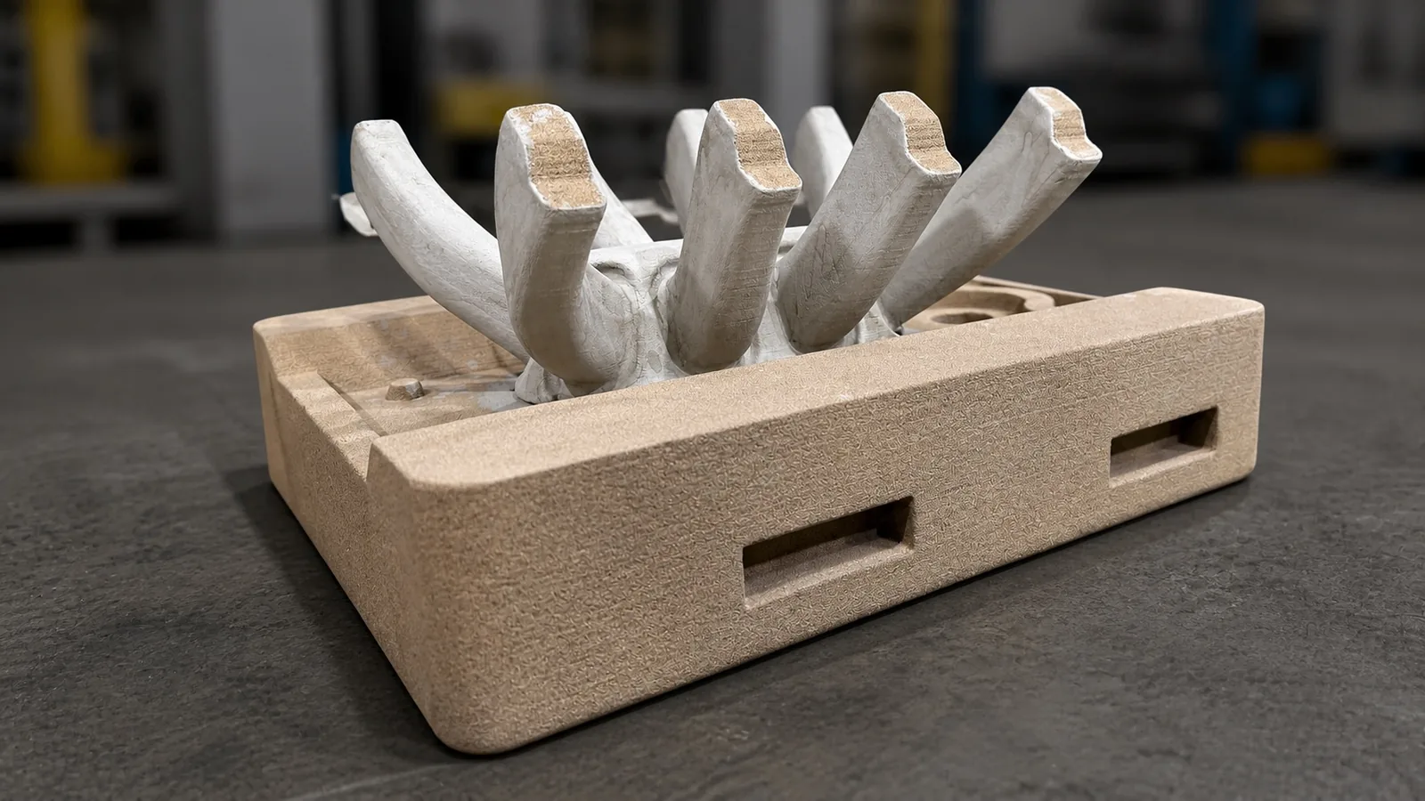
A hybrid route uses reusable pattern equipment for the conventional mould and 3D sand printing for a complex core or selected mould section — a documented way of integrating printing alongside existing conventional capacity.[2]
- Retains conventional tooling for repeatable, straightforward geometry
- Uses digital production only where geometric complexity justifies it
- Can reduce the need for complex core-box tooling
- Allows the process route to be selected component by component
Engineering note: a hybrid route adds a second production route to coordinate. The benefit depends on how much geometry genuinely requires printing.
Limitations of each route
3D sand printing
- Mould cost recurs with every build and does not fall with quantity in the way tooling cost does
- Component size is limited by the printer build volume; larger geometry must be segmented and assembled
- Build utilisation strongly influences cost per mould
- Requires controlled digital data, mould segmentation and depowdering, cleaning and coating discipline
- Throughput is constrained by printer capacity when several projects run in parallel
Traditional pattern making
- Tooling must be manufactured before the first mould, extending the front end of the schedule
- Design revisions may require modification or replacement of the pattern or core box
- Geometry must respect draft, parting and pattern-release constraints
- Complex internal passages may require multi-part core boxes and manual core assembly
- Patterns require storage, identification, maintenance and eventual replacement as they wear
Neither list disqualifies a route; both identify where engineering risk concentrates for review.
How Speed3D Mold evaluates a project
- Review available drawings, CAD, sample parts and service requirements
- Confirm material, quantity and repeat-demand expectations
- Identify critical geometry, cores and inspection requirements
- Evaluate traditional, printed and hybrid manufacturing routes
- Develop mould segmentation, gating and feeding concepts
- Use casting simulation where appropriate
- Compare production risk, total workflow and expected repeat demand
- Recommend a project-specific process route
Not every project requires every activity listed above. The depth of the review depends on the geometry, the material and the data available — for example, casting simulation of filling and solidification is applied where the feeding or filling behaviour carries real risk, and 3D sand printing of moulds and cores is only proposed where it fits the component. Completed examples are documented in our casting case studies.
Information required for assessment
- Existing component or sample
- 2D drawing or 3D CAD, if available
- Required material
- Estimated quantity
- Expected repeat-order frequency
- Required delivery date
- Approximate dimensions and weight
- Internal passages and core requirements
- Critical dimensions
- Machining requirements
- Inspection and documentation requirements
- Service conditions, where relevant
- Known failure or replacement reason
- Likelihood of future design changes
Where drawings no longer exist, our separate guide sets out the information needed to reproduce a cast part without original drawings.
Frequently asked questions
Conclusion
3D sand printing is not automatically correct for every casting, traditional patterns remain valuable for stable repeat production, and hybrid production can suit geometry that only partly requires printing. Select on the complete workflow — total project cost, schedule risk, geometry, available data and repeat demand — rather than tooling cost alone.
References
- Hawaldar, N. and Zhang, J. (2018). A comparative study of fabrication of sand casting mold using additive manufacturing and conventional process. The International Journal of Advanced Manufacturing Technology. doi.org/10.1007/s00170-018-2020-z
- Sama, S. R., Badamo, T. and Manogharan, G. (2019). Case Studies on Integrating 3D Sand-Printing Technology into the Production Portfolio of a Sand-Casting Foundry. International Journal of Metalcasting. doi.org/10.1007/s40962-019-00340-1
- Henderson, H. B., Stromme, E. T., Kesler, M. S., et al. (2020). Additively Manufactured Single-Use Molds and Reusable Patterns for Large Automotive and Hydroelectric Components. International Journal of Metalcasting, 14, 356–364. doi.org/10.1007/s40962-019-00379-0
Cited results describe the components, equipment and conditions of the published studies and do not represent Speed3D Mold project outcomes.
Evaluate the Right Moulding Route for Your Project
Share the available part data, required quantity, material and delivery requirement. Our engineering team can review whether a printed, traditional or hybrid moulding route should be considered.