
Important: Reverse engineering records the condition of the available part, not the original design intent. Worn or damaged geometry should not be copied automatically; missing geometry may require engineering reconstruction, and any value that cannot be supported by evidence must be identified as an assumption and approved before production. Wear allowance, machining allowance, fits and functional surfaces are evaluated rather than copied.
The minimum information needed for an initial assessment
Send as much of the following information as is available.
Photographs
Multiple angles of the complete part, with a ruler or known object for scale.
Overall dimensions
Length, width, height and the largest diameter.
Part function
What the component does and where it is installed.
Sample condition
Whether the sample is complete, worn, cracked, corroded, distorted or missing sections.
Material information
Any grade, certificate, manual or previous laboratory report.
Operating conditions
Fluid or environment, temperature, pressure, speed and load where relevant.
Recommended photo angles
Front, rear, top, bottom and both sides; close-ups of worn or damaged regions; part number, nameplate and casting marks; shaft, bore, flange, bolt pattern and sealing interfaces; internal passages where visible; fragments, previous repairs or welded regions.
Full dimensional requirements
Overall envelope, largest diameter, approximate weight, wall thicknesses, centre distances, bore and shaft sizes, flange and bolt-circle dimensions, plus any known critical tolerances.
Operating conditions in detail
Fluid or environment, operating and peak temperature, working pressure, rotational speed, applied load and duty cycle, together with corrosion, erosion or abrasion exposure.
Supporting documents
Equipment manual, parts list, historical purchase record, previous material certificate, earlier laboratory report and any maintenance or repair history.
Mating-part information
Geometry, clearances and fits of the components the part connects to: bearing seats, shaft fits, flange faces, bolt patterns and sealing surfaces.
Inspection records
Any dimensional report, chemical analysis, mechanical test, NDT result or customer-specific acceptance requirement, plus the documentation needed on delivery.
Quantity required
A one-off emergency replacement and a repeat-production requirement may need different manufacturing plans.
Delivery requirement
Give the required-on-site date and explain whether the equipment is already out of service.
This information does not guarantee that the part is ready for manufacture. It allows the engineering team to identify missing data and propose the next verification steps.
What information is most useful?
The list below is a general ordering of how useful each type of evidence usually is. It is not a rigid universal ranking: usefulness depends on the component, its condition, its function and the project requirements.
- 1
Existing physical component
Allows direct measurement, interface checks and, where appropriate, material sampling.
- 2
Damaged or incomplete component
Still carries interfaces, wall sections and reference features that support reconstruction.
- 3
Previous drawings, sketches, manuals or records
Provide nominal dimensions, part identity and assembly context for comparison with the part.
- 4
Existing CAD or scan data
Represent measured or previously modelled surfaces that still require interpretation and verification.
- 5
Critical dimensions and mating-component information
Define the fits and interfaces the replacement must satisfy in the installed assembly.
- 6
Material information or material evidence
Certificates, purchase records or a physical sample give a basis for material evaluation.
- 7
Operating and service conditions
Establish the functional requirements the component must meet in service.
- 8
Photographs and maintenance history
Support identification, configuration understanding and separation of wear from original geometry.
Evidence matrix
No single input replaces every function of a controlled engineering drawing. Several evidence sources are normally combined.
| Available evidence | What it can help establish | What may still be missing |
|---|---|---|
| Complete physical sample | 3D scanning, manual measurement, feature reconstruction | Original unworn dimensions, tolerances and design intent |
| Worn or damaged sample | Partial geometry, interfaces and remaining reference features | Repair of missing geometry, wear compensation and symmetry assumptions |
| Broken fragments | Local surfaces, wall thickness and fracture interfaces | Alignment, missing sections and cause of failure |
| Photographs with scale | Initial size and complexity assessment | Accurate geometry, hidden features and tolerances |
| Equipment manual or parts list | Part identity, nominal material or assembly context | Current revision and actual installed condition |
| Mating component | Interface geometry and clearance evaluation | Intended operating fit and wear allowance |
| Previous material certificate | Candidate alloy and specification | Whether the certificate belongs to the submitted sample |
| Laboratory chemical analysis | Measured elemental composition of the tested location | Final grade selection, mechanical properties and service suitability |
| New customer specification | Required performance and acceptance criteria | Manufacturability and compatibility with the existing assembly |
What the existing component itself can show
An existing component is often the most direct evidence available. It can show overall geometry, mounting interfaces, mating surfaces, critical features, wear patterns and evidence of previous machining. What it shows is the measured existing condition, which is not the same as the original design condition. Worn or distorted geometry should be evaluated rather than copied.
Complete physical sample
The strongest starting point. Supports scanning, manual measurement and feature reconstruction; original unworn dimensions and tolerances still need engineering confirmation.
Worn or damaged sample
Gives interfaces and remaining reference features. Missing geometry, wear compensation and symmetry must be reconstructed and approved.
3D scan or CAD data
Provides measured surfaces. Alignment, feature interpretation and allowances are required before it becomes a controlled model.
Photographs and equipment records
Enough for an initial size, complexity and part-identity assessment, but not for accurate geometry, hidden features or tolerances.
Can a worn or broken part still be reverse engineered?
Often, yes—but the reconstruction method depends on what remains.
Measured geometry
Surfaces captured directly from the available part in its current condition, including wear and damage.
Reconstructed geometry
Features restored from symmetry, repeated features, fragments, mating components or undamaged counterparts where that evidence justifies it.
Assumptions requiring confirmation
Anything not supported by evidence. Missing design intent cannot always be recovered; every assumption must be documented and approved before production.
Engineers compare opposite or repeated features, use symmetry where justified, inspect mating components and align fragments to recover reference geometry, as part of our reverse engineering services. Maintenance records — previous clearances, repair dimensions and photographs taken before damage — help separate original geometry from service wear.
Do not discard damaged fragments before the assessment. A small section may preserve a critical radius, wall thickness, bolt position or fracture surface.
Missing geometry must not be invented without an engineering basis. Where reconstruction requires an assumption, that assumption is identified, recorded and reviewed before it is used.
What cannot be known from the part alone
Physical inspection and measurement establish the current condition of the component. The following information usually cannot be determined with certainty from the part by itself, and has to come from records, equipment documentation, functional review or an approved engineering assumption.
- Original nominal dimensions before service wear
- Original tolerances and their intended function
- Original design intent and safety margins
- Original material specification and heat-treatment history
- Original casting and machining allowances
- Undocumented modifications, repairs or field changes
- The complete operating and maintenance history of the component
How geometry is reconstructed
The workflow moves from available evidence to an approved model and a verified casting.
- 01
Initial evidence review
Photos, dimensions, records and sample condition are checked.
- 02
Measurement and geometry capture
Manual instruments, coordinate or optical measurement as appropriate.
- 03
CAD reconstruction
Measured data become a controlled model with datums and allowances.
- 04
Engineering and customer verification
Critical dimensions, assumptions and material are approved.
- 05
Production and dimensional inspection
The approved route is executed and results verified against agreed criteria.
Peer-reviewed work involving Speed 3D Mold reports that, when drawings are unavailable, 3D scanning of old parts can provide data for 3D sand printing of moulds. The paper describes replacement applications in Thailand and explains that patternless 3D sand printing can remove the need for patterns or core boxes and reduce production lead time. Our earlier replacement casting research covers the same approach, and the peer-reviewed source is listed in the references below.
How an unknown material is assessed
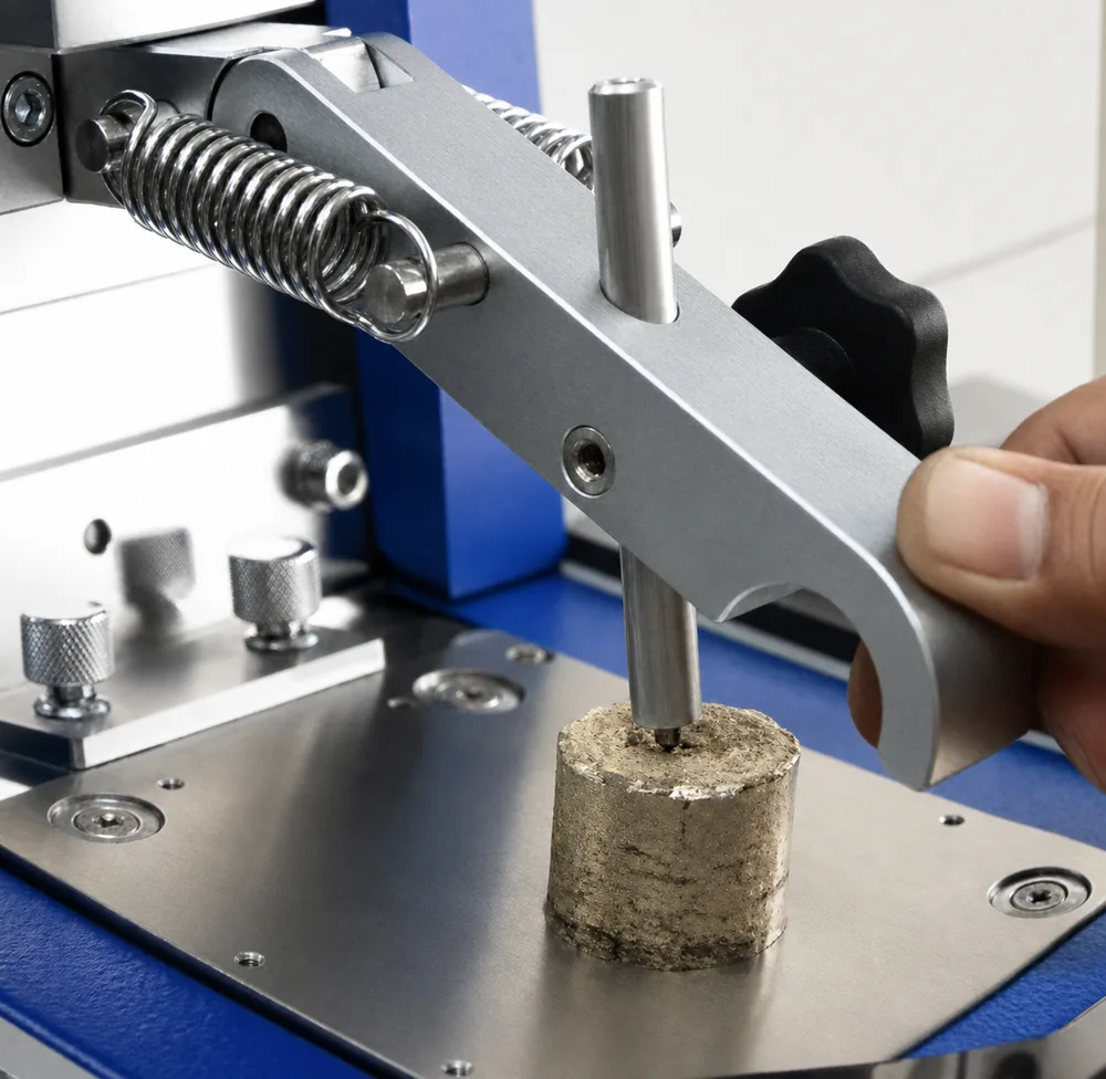
Colour, weight, a spark test or a handheld reading may provide clues, but appearance alone is not sufficient to assign a material grade.
Evidence used
- Chemical composition testing suited to the alloy family;
- Material grade evidence from records, certificates and service history;
- Corrosion and wear conditions in service;
- Pressure, temperature and applied load;
- Service environment and duty;
- Comparison with the applicable material specification.
Spectrometer analysis measures composition at the tested location. On its own it does not confirm mechanical properties, heat-treatment condition or service suitability.
If the original grade cannot be verified, the proposed material is presented as an engineering selection—not as the confirmed original material—and requires customer approval before production.
Decision guide
A general guide to the next engineering step for common situations. It indicates what happens next, not whether a specific part can be reproduced.
| Situation | Recommended next step |
|---|---|
| Complete component available | Begin physical engineering assessment: measurement, interface review and material evidence. |
| Damaged or incomplete component available | Determine whether the surviving evidence is sufficient, and identify what must be reconstructed. |
| Only photographs available | Request additional dimensional or physical evidence before geometry can be established. |
| Old drawing available | Verify the drawing against the existing component and installed equipment condition. |
| Existing CAD or scan data available | Review alignment, feature interpretation and allowances before the data are treated as controlled geometry. |
| Material unknown | Determine what records, certificates or analysis are required for a material basis. |
| Critical information unavailable | Engineering review is required before feasibility can be confirmed. |
What must be confirmed before production
The following items should be resolved before the mould or production route is released.
Geometry and interfaces confirmed
Approved CAD revision, datum system and all mating interfaces.
Material basis reviewed
Grade, specification and any qualification testing agreed.
Critical dimensions and tolerances defined
Stated explicitly rather than inferred from scan data.
Casting and machining allowances established
Cast and machined surfaces separated, with allowances defined.
Manufacturing approach reviewed
Casting, heat-treatment and machining route agreed for the quantity required.
Inspection requirements agreed
Inspection plan, acceptance criteria, documentation and traceability.
Common mistakes when reproducing a casting without drawings
Copying worn geometry directly
Measured surfaces record the current condition. Wear, corrosion and distortion should be evaluated before the geometry is accepted as the design geometry.
Assuming material from appearance
Colour, weight or a spark test may narrow the alloy family, but they do not establish a grade or its specification.
Ignoring mating components
Fits, clearances and bolt patterns are defined by the assembly, not by the part in isolation.
Treating photographs as dimensional evidence
Photographs support identification and configuration review; they do not normally establish manufacturing geometry.
Overlooking machining allowances
Cast and machined surfaces need to be distinguished so that allowances are defined rather than inherited from a finished part.
Manufacturing before requirements are verified
Critical dimensions, material basis and acceptance criteria should be agreed before the production route is released.
Key takeaways
- Original drawings are useful, but they are not the only possible source of engineering evidence.
- An existing, damaged or incomplete component may still provide valuable geometric and interface information.
- Measured geometry may represent worn condition rather than the original design condition.
- Material and operating requirements normally have to be established separately from geometry.
- Information that cannot be supported by evidence should be recorded as an assumption, not guessed.
- Engineering review determines whether the available evidence is sufficient to proceed.
Customer submission checklist
Tick the items you already have. Your selections stay in this browser tab only—nothing is collected, transmitted or stored.
What to photograph
- All sides, plus close-ups of worn or damaged regions;
- Part number, nameplate and casting or material markings;
- A ruler or tape measure in at least one overall photograph;
- Shaft, bore, flange, bolt-pattern and sealing interfaces;
- Fragments, previous repairs or welded regions.
Photographs support screening but do not replace measurement.
A review of the available evidence only; not a feasibility confirmation or a quotation.
Frequently asked questions
Related case studies
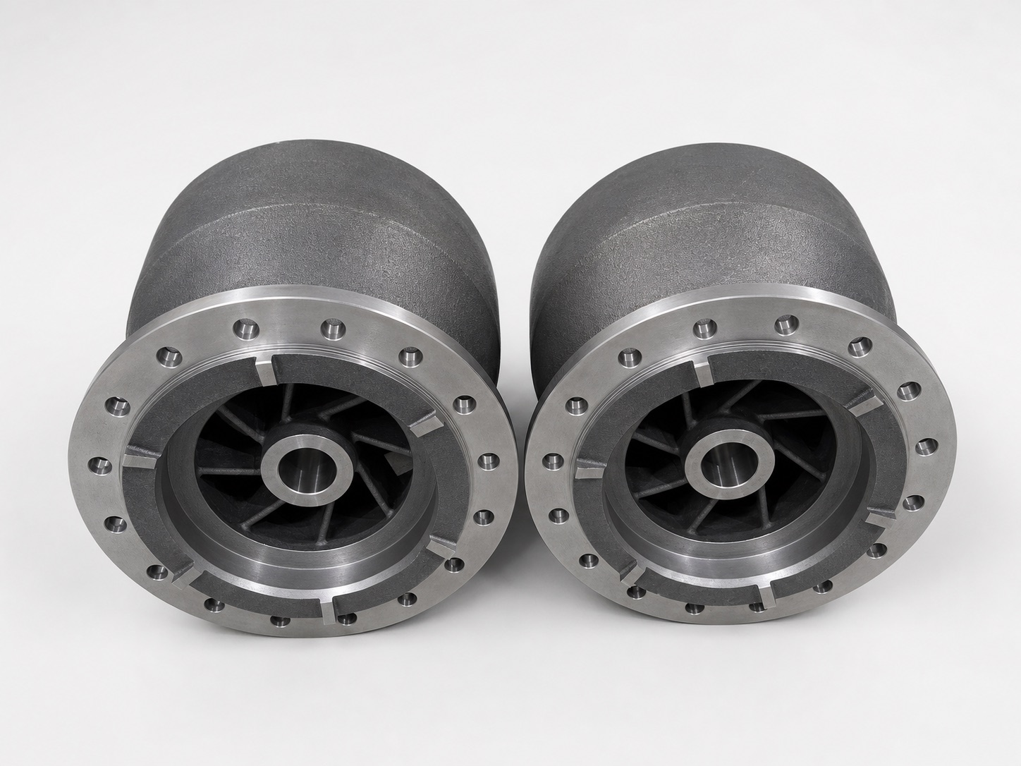
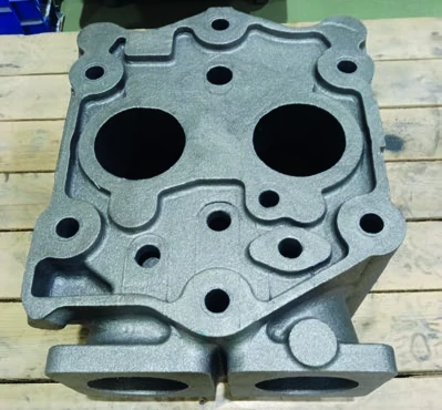
These are specific project examples, not a guarantee of typical lead time or performance.
Related research
Published work involving Speed 3D Mold that relates to reproducing components without original design data.
- Trade journal article · 2017Using 3D Sand Printing Technology in Part ReplacementDocuments replacement components produced from scanned existing parts where drawings were unavailable.
- Journal article · 2016Reverse Engineering Through Patternless Casting (T.991 marine propeller)Describes reconstructing a marine propeller from the physical component rather than from original design data.
- Trade journal record · 2014Replacement Casting for the FSO JasmineA reported replacement casting project for offshore equipment based on the existing component.
Related engineering resources
- Replacement casting
The overall service context for reproducing obsolete and unavailable cast components.
- Reverse engineering
The full methodology used when geometry must be recovered from a physical component.
- 3D scanning
How non-contact geometry capture is performed and what the resulting data represent.
- CAD verification
How a reconstructed model is checked against the part, interfaces and agreed assumptions.
- Materials
How material grades are evaluated, specified and verified for cast components.
- Casting simulation
How filling and solidification behaviour is assessed before a production route is released.
- Case studies
Documented projects, including obsolete and replacement components.
Sources
Not sure whether you have enough information?
Send whatever is available — photographs, old drawings, measurements, component and equipment information, and any material records — for an initial engineering review of the evidence. Not every component can be reproduced; that depends on the available evidence and the engineering review of it.