Can a damaged marine propeller be used for reverse engineering?
It can provide useful measured geometry and interface information, subject to an engineering review of what remains usable and what must be reconstructed.

ISO 9001:2015 Certified by SGS
Certified Quality Management SystemMarine Replacement Case Study · C95800 Propeller
A damaged physical propeller became the engineering reference for producing one 1,200 mm replacement in ASTM B148 C95800 nickel aluminium bronze. The project combined 3D scanning, CAD reconstruction, casting simulation, a 26-section 3D-printed sand mould system, casting, finishing and dynamic balancing before the completed propeller entered operational service.
Selected project information is presented without the customer identity, vessel designation, drawings or confidential technical data.
The Replacement Challenge
A damaged physical propeller was the available starting reference, and the original pattern tooling was not available. The replacement geometry therefore had to be reconstructed from the existing component.
Damaged areas could not simply be copied into the manufacturing model. The project required manufacturable geometry and a mould system for a large C95800 casting, followed by the finishing, hub work and dynamic balancing needed before operational use.
Engineering Reconstruction
3D scanning records physical geometry as measured. Engineering review then separates usable reference geometry from damaged or degraded areas before CAD reconstruction creates a manufacturable definition.
Hub and shaft-connection relationships, blade-to-hub relationships, principal dimensions and installation interfaces were reviewed together with the casting and finishing requirements.
The damaged condition was not copied directly. Usable reference geometry was separated from areas requiring reconstruction and engineering review.
Casting Engineering
Casting simulation was used to review the proposed casting system before mould production, including filling behaviour, solidification sequence, proposed gating and feeding arrangements, and areas requiring attention during process planning.
The simulation supported review of the proposed casting process before the mould sections were printed. It did not guarantee a defect-free casting.
Mould Production
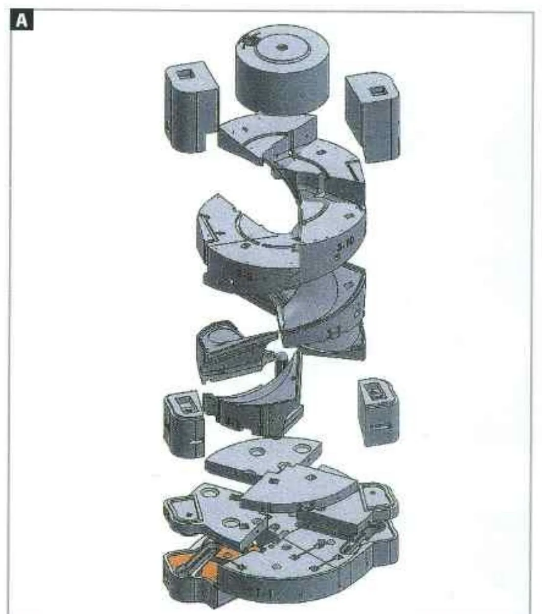
The large and complex sand mould geometry was divided so it could be produced within the available print envelope. The organised sections were binder-jet printed and assembled into one complete mould package before pouring.
Mould-printing record: 26 sand mould sections printed in five days. This is the printing time for the mould sections, not the total propeller manufacturing or delivery time.
The 26 pieces were printed sand mould sections. The metal propeller was not manufactured as 26 separate pieces.
Engineering-to-Manufacturing Workflow
Review the physical propeller and identify usable reference geometry.
Capture the existing propeller geometry as measured digital data.
Reconstruct manufacturable geometry without copying damaged areas directly.
Prepare the component and casting-system geometry for mould production.
Review the proposed filling, feeding and solidification behaviour before printing.
Binder-jet print the separate sand mould sections directly from prepared digital data.
Assemble the 26 printed sections into the complete mould package.
Cast the propeller in ASTM B148 C95800 nickel aluminium bronze.
Complete the required finishing and hub-related work.
Perform dynamic balancing before operational use.
Place the completed replacement propeller into service.
Project Evidence Gallery
These figures are from the matching 2017 technical record. No confidently attributable damaged-reference, scan, CAD or simulation image is available for this page.
Detailed historical inspection, balancing and operational records from this earlier project are not presented on this page.
Engineering Boundary
Every marine replacement project is reviewed individually. Geometry, alloy, casting process, inspection requirements, balancing scope and project timing depend on the condition of the reference component, the available engineering information and the vessel requirements. Results from this project should not be treated as a standard lead-time or performance guarantee for other propellers.
It can provide useful measured geometry and interface information, subject to an engineering review of what remains usable and what must be reconstructed.
No. Scanning records the physical condition as measured. Damage and degradation are separated from usable reference geometry during CAD reconstruction and engineering review.
Binder-jet 3D sand printing produced the separate sand mould sections. It did not print the metal propeller.
Sectioning allowed the large, complex mould geometry to be produced within the available print envelope and then assembled into one complete mould package.
Yes. The 26 pieces were sand mould sections; the C95800 metal propeller was cast as one component in the assembled mould.
Yes. Simulation supported review of the proposed filling, feeding and solidification behaviour before mould production. It was an engineering review tool, not a guarantee of a defect-free casting.
Yes. Dynamic balancing was performed before the completed propeller entered operational service. Detailed historical balancing records are not presented here.
No. The route depends on the condition of the reference, available engineering data, alloy, inspection and balancing scope, installation requirements and project timing.
Provide available photographs, principal dimensions, material information, scan or CAD data if available, required quantity, finishing scope, inspection requirements and operational context for an initial engineering review.
Technology Representation

Speed 3D Mold Co., Ltd. is listed by ExOne as a sales representative in Thailand, supporting local coordination for industrial sand 3D-printing solutions.
Verify our listing on ExOne’s official global support network.
View Official ExOne Listing