
Pump Replacement Casting Engineering
Reproducing obsolete, worn and difficult-to-source cast pump components through a connected engineering workflow: assessment of the existing part, dimensional capture, CAD reconstruction, casting simulation, patternless mold production, casting and inspection. The applicable stages depend on the component condition, geometry, material and the information available.
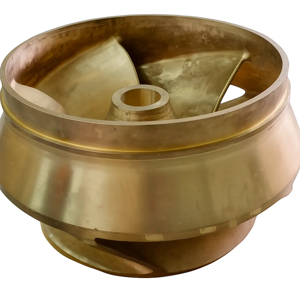
When the Pump Still Matters but the Original Manufacturing Data Does Not
A pump can remain in service long after its manufacturing record has been dispersed. The engineering task is rarely "make a casting". It is to reconstruct the component, determine a manufacturable casting geometry, review the casting process, produce the required mold and core system, cast the component and verify the result against the requirements agreed for the project.
- OEM support for the pump model has been discontinued or the component is no longer catalogued.
- The original casting pattern or core boxes no longer exist or cannot be located.
- Drawings are incomplete, superseded, or were never released to the operator.
- The only reference is the worn, cracked, or corrosion-damaged component removed from service.
- Only one or a small number of replacement castings are required.
- The component has curved blade geometry and internal passages that are difficult to reproduce from measurement alone.
- Dedicated pattern tooling can be difficult to justify commercially for a single replacement casting.
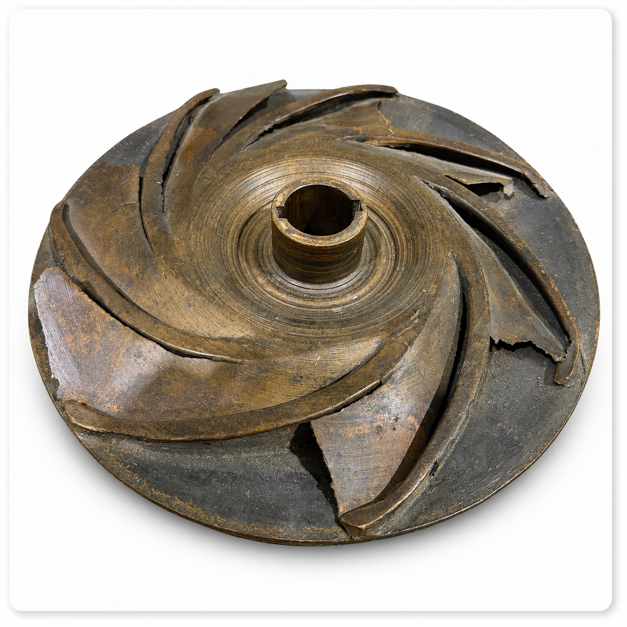
What Information Can Start a Replacement Project?
Projects start from different combinations of information. No single input guarantees that a component can be reproduced; the available data determines which engineering stages are required and what has to be established before manufacturing can be planned.
Existing physical component
The removed part, even when worn or damaged, is usually the most informative starting point.
Drawings, if available
General arrangement drawings, sectional drawings or dimension sheets, including superseded revisions.
Scan or CAD data
Previously captured 3D scan data or CAD models supplied by the operator or a third party.
Material specification
The specified alloy or standard, or the information needed to agree one for the application.
Application information
Pump type, service medium, and operating conditions relevant to material and geometry decisions.
Quantity and inspection requirements
The number of castings required and any dimensional, material or documentation evidence expected.
Where drawings are unavailable, see replacement casting without original drawings for the information hierarchy used to evaluate such projects.
From Existing Component to Replacement Casting
Each stage has defined inputs and outputs. Not every project uses every stage; the applicable stages and the inspection scope are agreed for each project.
- 01
Existing Component Assessment
- Input
- Removed component, photographs, available drawings, application information.
- Activity
- Review the condition of the reference part, identify wear, cracking and corrosion damage, and establish which surfaces remain usable as engineering references.
- Output
- An assessment of what geometry can be recovered and what additional information is required.
- 02
3D Scanning and Dimensional Capture
- Input
- Physical component and the identified reference surfaces.
- Activity
- Capture the component geometry as measured data, supported by manual dimensional checks on interfaces that must match the existing pump assembly.
- Output
- Measured geometry representing the part in its current, as-removed condition.
- 03
CAD Reconstruction and Engineering Review
- Input
- Measured geometry, drawings where available, application requirements.
- Activity
- Reconstruct the component as engineering geometry. Worn and damaged regions are interpreted rather than copied, and mounting and machining interfaces are reviewed against the existing pump.
- Output
- A reconstructed CAD model intended as a manufacturable casting geometry.
- 04
Casting Simulation
- Input
- Casting geometry, proposed rigging layout, material and process assumptions.
- Activity
- Evaluate mold filling, solidification and feeding behaviour to identify areas that require engineering review before production.
- Output
- A reviewed rigging and feeding approach for the replacement casting.
- 05
Patternless Mold and Core Production
- Input
- Approved mold and core data generated from the reviewed casting design.
- Activity
- Produce sand molds and cores directly from digital data by binder jetting where this route is appropriate for the geometry, size and quantity.
- Output
- A mold-and-core package prepared for pouring.
- 06
Metal Casting
- Input
- Assembled mold package and the agreed material specification.
- Activity
- Prepare material, pour the casting and carry out fettling according to the agreed manufacturing plan.
- Output
- An as-cast replacement pump component.
- 07
Inspection and Verification
- Input
- As-cast component and the agreed inspection scope.
- Activity
- Verify the dimensions, material and any additional checks defined for the project scope, such as fit against the existing pump assembly.
- Output
- Inspection and process evidence agreed for the project.
Why Pump Components Can Be Difficult to Reproduce
Curved blade geometry
Impeller blades are three-dimensional surfaces that cannot be reliably described by a small number of measured dimensions.
Internal passages
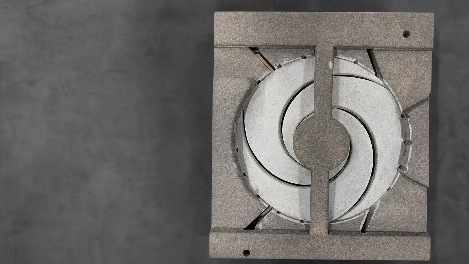
Closed impellers, casings and bowls contain enclosed flow passages that must be formed by cores rather than by the mold cavity alone.
Core complexity
The core package, not the outer shape, is often the limiting factor in reproducing a cast pump component.
Worn reference surfaces
Cavitation, erosion and corrosion remove material, so measured geometry represents the worn condition rather than the original design intent.
Feeding and solidification
Section changes between hub, shroud and blades affect feeding, which is why the casting design is reviewed before production.
Interfaces and inspection
Mounting and machining interfaces must remain compatible with the existing pump assembly and with the inspection scope agreed for the project.
Pump Components That May Require Replacement Engineering
The documented evidence on this site is strongest for impellers. Other cast pump components are represented by individual documented projects.
Impellers
Closed and open impellers, including large-diameter replacement impellers, are the most extensively documented pump component on this site.
Impeller componentsPump bowls
A steel pump bowl was produced through a documented CAD, rigging, simulation, printed-mold and machining workflow.
Steel pump bowl case studyPump casings
A cast iron pump casing with complex internal passages was produced using printed molds and cores.
Cast iron pump casingOther cast pump components
Other cast pump parts can be reviewed individually, subject to geometry, material, quantity and available reference information.
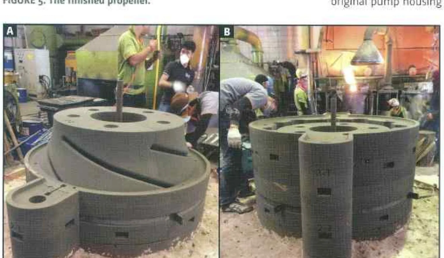
Replacement castingDocumented Replacement Engineering: Vertical Pump Impeller
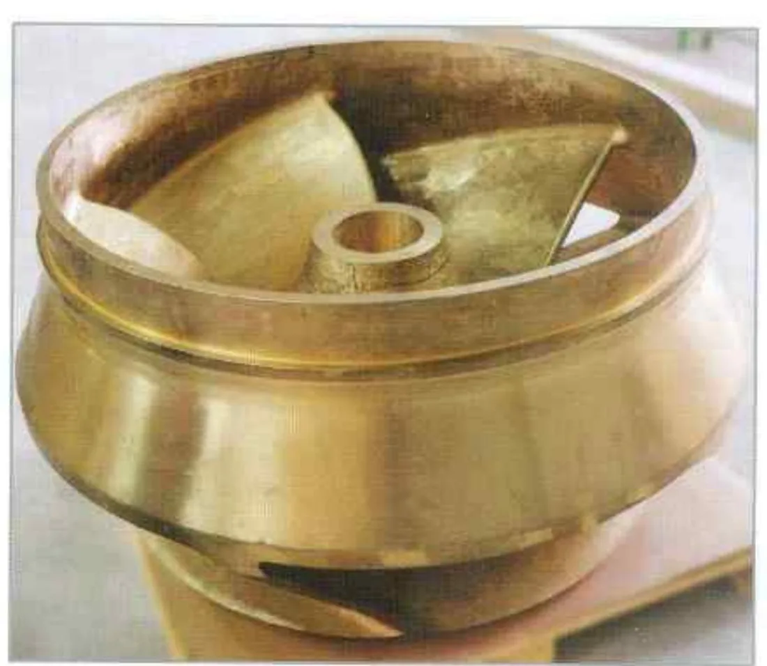
A cracked, cavitation-corrosion-damaged impeller in a vertical pump more than 20 years old had to be replaced, with no spare parts available and no budget for a complete new pump unit. The replacement had to fit the original pump housing and auxiliaries. The mould was designed, printed, assembled and poured as a one-off, and machining was carried out by the customer. This project is described in a published technical paper.
- Component
- Vertical pump impeller
- Finished diameter
- 1,270 mm
- Weight
- 900 kg
- Material
- Aluminium bronze
- Reference condition
- Cracked and cavitation-corrosion damaged impeller in a pump over 20 years old
- Manufacturing route
- One-off mould designed, printed, assembled and poured
Reconstructing Geometry Is Not the Same as Copying Wear
Measurement records the component as it is now. A worn impeller has lost material at exactly the surfaces that matter most, so measured data alone does not describe the geometry the pump was built around. The reconstruction moves through defined steps: physical measurement, engineering interpretation of worn and damaged regions, reconstructed CAD, and finally a casting-ready geometry that accounts for the requirements of the casting process.
Interfaces that must match the existing pump assembly are treated separately from surfaces that are reconstructed, because those are the dimensions the operator depends on during installation.
Reverse engineering for cast components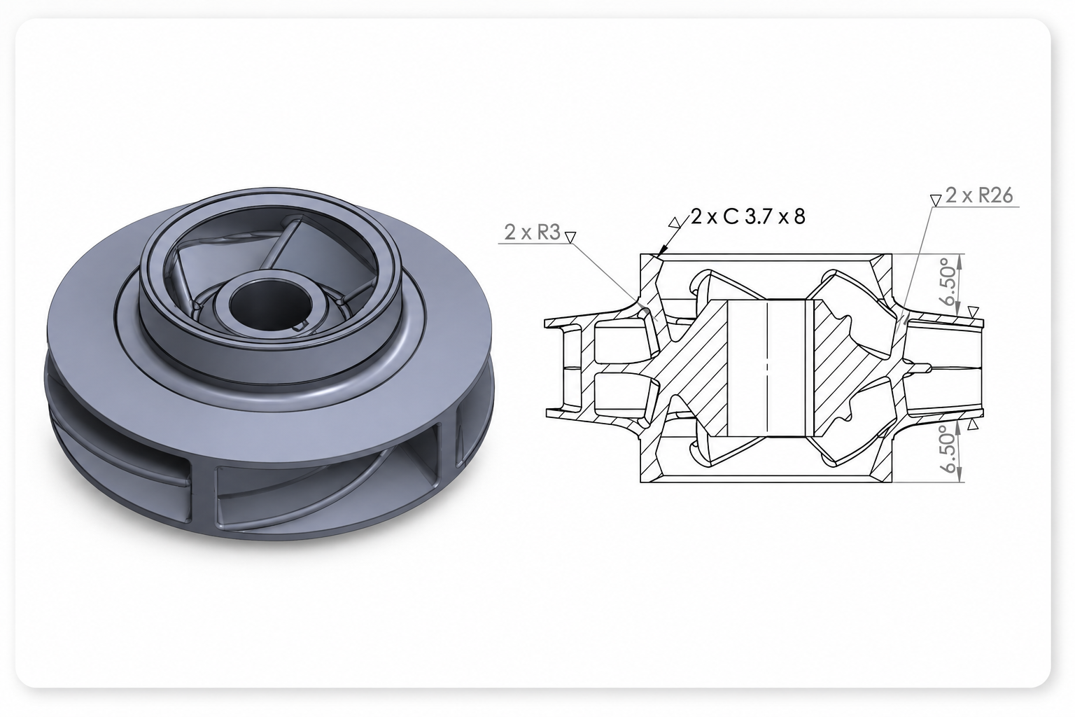
Evaluate Casting Manufacturability Before Production
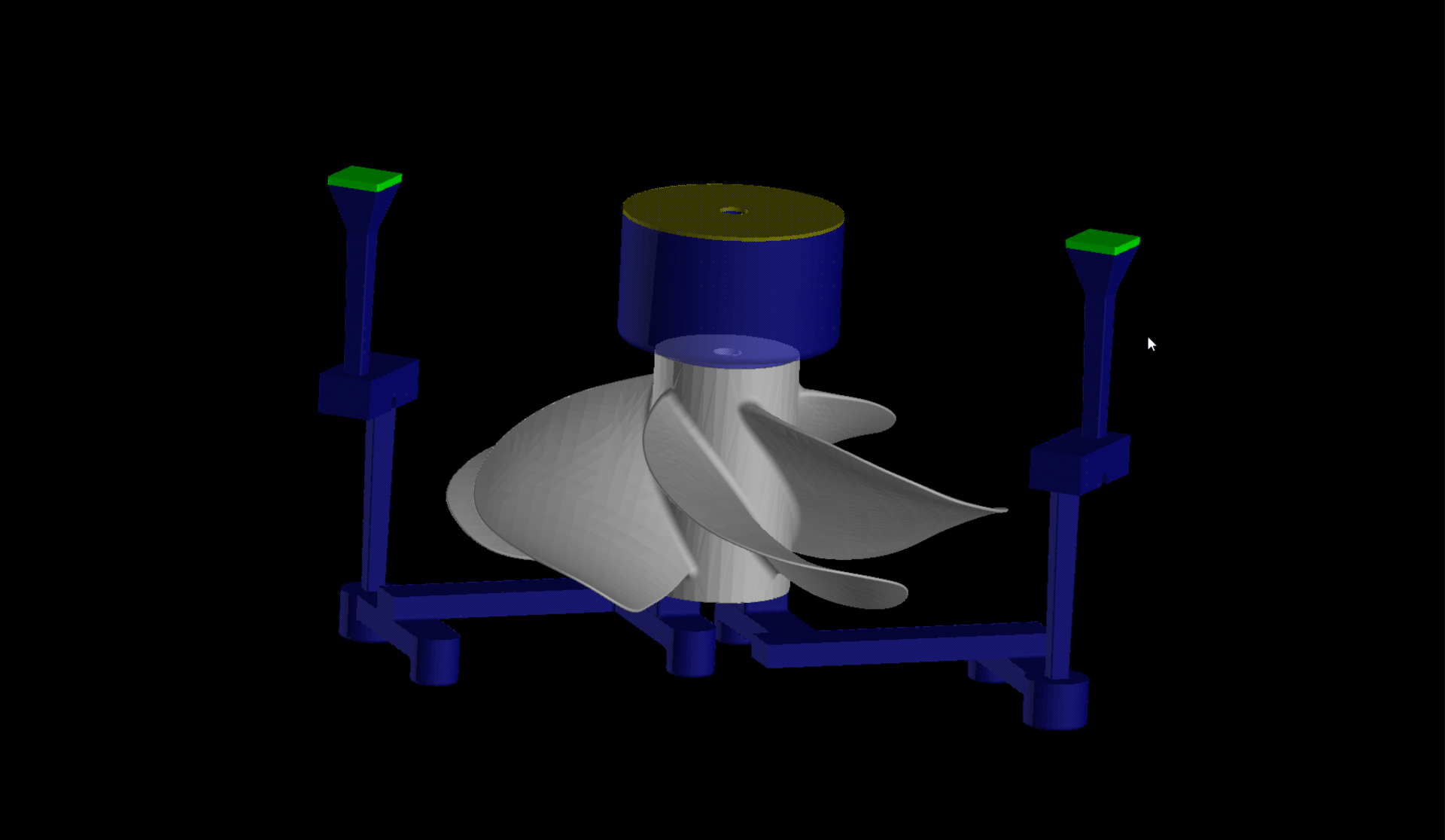
Simulation is used to examine filling behaviour, solidification and feeding for the proposed casting design, and to identify areas that require engineering review. It is a decision-support activity based on the geometry, rigging layout and process assumptions supplied to it, not a guarantee of casting outcome.
For a replacement component this matters because the rigging design cannot be inherited from an existing pattern; it has to be developed for the reconstructed geometry.
Casting simulationWhen Conventional Pattern Tooling Is Not the Best Starting Point
Sand molds and cores produced by binder jetting are generated directly from approved digital data. For replacement work this can support one-off and low-volume production, complex core packages, projects where no pattern exists, and engineering iteration between the CAD model and the mold data.
Patternless production is not automatically faster or lower cost. Suitability depends on the geometry, component size, quantity, material and the requirements of the project.
Patternless manufacturing and 3D sand printingMaterial Selection Starts With the Application
The alloy for a replacement component is normally defined by the original specification, the service medium and the operator's requirements rather than chosen independently. Documented pump projects on this site include an aluminium bronze vertical pump impeller, a lead-tin bronze double-suction impeller, an FC300 gray cast iron impeller and a cast iron pump casing.
Where the specification is unknown, it has to be established before manufacturing can be planned.
Materials libraryWhen This Approach Makes Sense
- The original component is obsolete or no longer supported by the OEM.
- The original pattern or core boxes are unavailable.
- Only one or a small number of castings are required.
- A physical reference component, or usable drawing or scan data, is available.
- The component has complex cast geometry with internal passages or curved blades.
- Replacement timing is commercially important to the operator.
When More Engineering Information Is Required
- The reference component is missing sections that cannot be reconstructed from the remaining geometry.
- The required material or inspection standard has not yet been defined.
- Interfaces with the existing pump assembly cannot be measured or verified.
- Quantities are high enough that a conventional tooling route should also be evaluated.
Not every damaged component can be reproduced. Feasibility is established through engineering review of the actual part and the available data.
Engineering Evidence and Related Resources
- Vertical pump impeller replacement project
- Double-suction impeller casting case study
- FC300 impeller casting case study
- Replacement casting services
- Replacement casting without original drawings
- Reverse engineering for cast components
- Casting simulation
- Patternless manufacturing and 3D sand printing
- Materials library
- Published paper: 3D sand printing for part replacement
- Published paper: helical sprues in 3D sand printed moulds
Technology Representation

ExOne Sales Representative in Thailand
Speed 3D Mold Co., Ltd. is listed by ExOne as a sales representative in Thailand, supporting local coordination for industrial sand 3D-printing solutions.
Verify our listing on ExOne’s official global support network.
View Official ExOne ListingMEMBERS & SOCIETIES


Frequently Asked Engineering Questions
Can a pump impeller be reproduced without the original drawing?
In many cases the physical component can be used as the primary engineering input. The geometry is captured by measurement and 3D scanning and then reconstructed as CAD. Whether reproduction is feasible depends on how much usable geometry remains and on the interfaces that must match the existing pump.
Can a worn impeller be used for reverse engineering?
A worn component can be used as a reference, but the measured surfaces represent the worn condition. The reconstruction therefore requires engineering interpretation of eroded, cracked or corroded regions rather than a direct copy of the scan data.
Is an original casting pattern required?
Not where a patternless route is suitable. Sand molds and cores can be produced directly from approved digital data. Suitability depends on the geometry, size, material and quantity of the component.
When does 3D sand printing make sense for pump replacement castings?
It is most relevant for one-off or low-volume replacement work, complex core packages, and projects where no pattern exists. It is not automatically faster or lower cost than a conventional route; the comparison depends on the specific project.
Why use casting simulation before producing a replacement casting?
Simulation is used to evaluate mold filling, solidification and feeding for the proposed casting design, and to identify areas requiring engineering review. It supports the design decision; it does not guarantee a defect-free casting.
Can complex impeller geometry be produced without conventional core boxes?
Printed cores can form enclosed impeller passages that would otherwise require dedicated core boxes. The documented double-suction impeller project produced its mold-and-core packages from digital data.
What information is needed to evaluate a replacement pump casting project?
Typically photographs of the component, any available drawings or scan data, key dimensions, the material specification or application details, the required quantity, and any inspection or documentation expectations.
Need to Reproduce an Obsolete Pump Component?
Share what you have available and the project can be reviewed by engineering: photographs of the component, the existing part, drawings if they exist, key dimensions, material information, the required quantity, and the application or operating conditions. Feasibility, manufacturing route and timing are established after that review rather than beforehand.